Push-type displacement feedback pneumatic deviation correction mechanism of vibrating platform used under centrifugal environment

A displacement feedback, vibration table technology, applied in vibration testing, machine/structural component testing, measurement devices, etc., can solve the problem that the vibration table cannot be directly applied to the centrifugal environment, and achieves low axial stiffness, simple control, and low cost. Effect

Inactive Publication Date: 2010-12-15
ZHEJIANG UNIV
View PDF3 Cites 8 Cited by
  • Summary
  • Abstract
  • Description
  • Claims
  • Application Information

AI Technical Summary

Problems solved by technology

[0004] In order to overcome the shortcomings that the vibrating table in the prior art cannot be directly applied to the centrifugal environment, the present invention provides a push-type displacement feedback air pressure correction mechanism that enables the vibrating table to be directly applied to the centrifugal environment

Method used


Image

  • Push-type displacement feedback pneumatic deviation correction mechanism of vibrating platform used under centrifugal environment
  • Push-type displacement feedback pneumatic deviation correction mechanism of vibrating platform used under centrifugal environment
  • Push-type displacement feedback pneumatic deviation correction mechanism of vibrating platform used under centrifugal environment

Examples


Embodiment Construction

[0028] With reference to accompanying drawing, further illustrate the present invention:

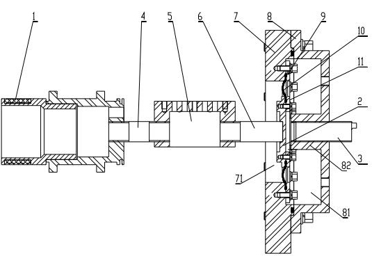
[0029] The push-type displacement feedback air pressure correction mechanism for a vibration table in a centrifugal environment includes a platform push rod 4 and a deviation correction push rod 6 symmetrically arranged at both ends of the vibration platform 5, and the platform push rod 4 and a driving vibration platform The reciprocating vibration vibration table moving part 1 linkage;

[0030] The deviation correction push rod 6 is linked with a deviation correction mechanism;

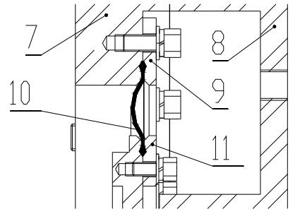
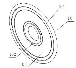
[0031] The deviation correction mechanism includes: a partition 2 affixed to the correction push rod 6, a closed hyperbaric chamber 8 located on both sides of the partition 2, and a low pressure chamber 7 connected to the atmosphere. The displacement sensor 3 of the cabin 8 and facing the partition plate 2 to monitor the displacement of the deviation correction push rod 6; the output signal of the displacement...


PUM


Abstract

The invention discloses a push-type displacement feedback pneumatic deviation correction mechanism of a vibrating platform used under a centrifugal environment. The mechanism comprises a platform push rod and a deviation correction push rod which are symmetrically arranged at the two ends of the vibrating platform, wherein the platform push rod is in linkage with a vibrating platform moving component which drives the vibrating platform to do reciprocating motion; the deviation correction push rod is in linkage with a deviation correction mechanism; the deviation correction mechanism comprises a partition plate, a closed high pressure chamber, a low pressure chamber and a displacement sensor; the partition plate is fixedly connected with the deviation correction push rod; the high pressure chamber and the low pressure chamber are positioned on the two sides of the partition plate respectively; the low pressure chamber is communicated with the atmosphere; the displacement sensor is positioned on the high pressure chamber opposite to the partition plate so as to monitor the displacement of the deviation correction push rod; an output signal of the displacement sensor is input to a controller; the high pressure chamber is provided with an air inlet and an air outlet; a charging electromagnetic valve and a discharging electromagnetic valve are controlled by the controller; the high pressure chamber is fixedly connected with the low pressure chamber; a high pressure cavity of the high pressure chamber interacts with a low pressure cavity of the low pressure chamber through the partition plate; and the partition plate is hermetically connected with the high pressure chamber through an annular sealing film. The mechanism has the advantages of directly applying the vibrating platform to the centrifugal environment.

Description

technical field [0001] The invention relates to a pushing type displacement feedback air pressure deviation correction mechanism used for a vibrating table in a centrifugal environment. technical background [0002] With the development of science and technology, the application environment of various electronic components is becoming more and more complex, and the requirements for the reliability of these components are getting higher and higher. In order to test the performance of the product in actual application, relevant environmental tests must be carried out before leaving the factory. However, the environmental test of a single factor cannot fully simulate the working environment of component products. In order to improve the accuracy of the environmental test, it is necessary to build a compound environmental accelerated test system, and to study the compound environmental test and the coupling between various environmental factors. [0003] The combination of lin...

Claims


Application Information

Patent Timeline
Patent Type & Authority Applications(China)
IPC IPC(8): G01M7/02
Inventor 沈润杰王春宇何闻贾叔仕
Owner ZHEJIANG UNIV
Why Eureka
Try Eureka