Digital display type drill rod and drill core tribometer
A technique for measuring friction and measuring instruments, which is applied in the direction of instruments, measuring devices, and mechanical devices, etc. It can solve problems such as large errors and unstable measurement values, achieve high accuracy, eliminate unstable effects, and have a wide range of applications
- Summary
- Abstract
- Description
- Claims
- Application Information
AI Technical Summary
Problems solved by technology
Method used
Image
Examples
Embodiment 1
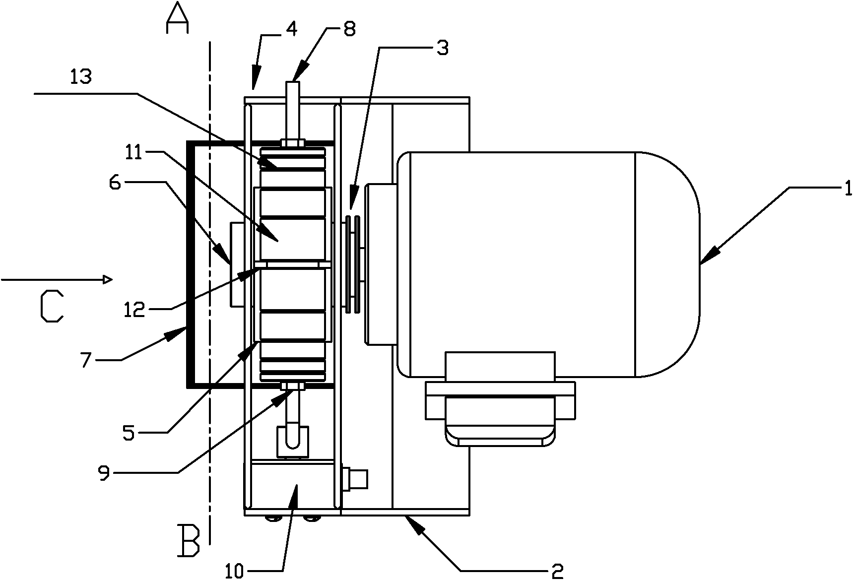
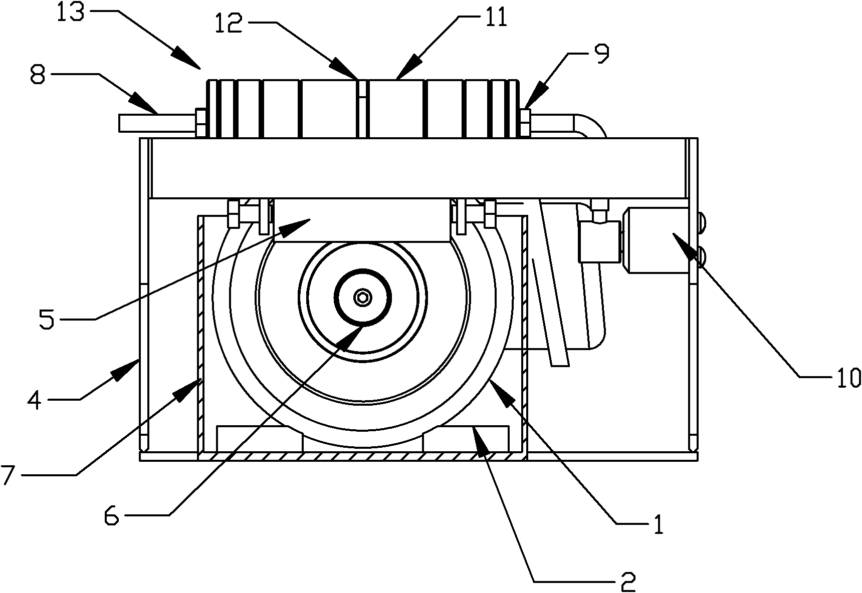
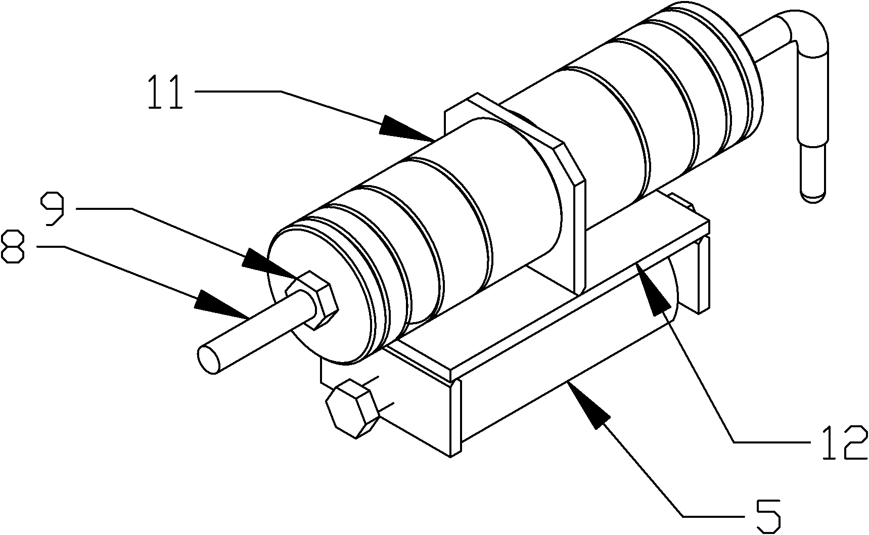
[0020] The digital display drill pipe and core friction tester is mainly composed of the following six parts (see Figure 1~3 ): motor 1, balance frame (i.e. support) 4, rock core clamping and pressurizing device 13 (see attached image 3 ), drilling fluid tank 7, simulated drill pipe 6 and sensor 10 (model: Hunan Aerospace GZB-2A).
[0021] The power of the motor is 75-100 watts, the linear speed of the outer edge of the simulated drill pipe is 1.61-3.06 m / s, and the measuring range of the sensor is 0-15N.
[0022] After the pressurization and clamping device are counterweighted, the guide rod 8 is connected to the sensor 10, and the sensor is leveled until the sensor shows zero. Note that the central axis of the sensor must be kept on a horizontal line with the contact surface between the core 12 and the simulated drill pipe 6. This reduces measurement errors and improves the accuracy of the device. After the preparatory work is completed, start the motor to drive the simu...
PUM
 Abstract
Description
Claims
Application Information
 - R&D
- Intellectual Property
- Life Sciences
- Materials
- Tech Scout
- Unparalleled Data Quality
- Higher Quality Content
- 60% Fewer Hallucinations
Browse by: Latest US Patents, China's latest patents, Technical Efficacy Thesaurus, Application Domain, Technology Topic, Popular Technical Reports.
© 2025 PatSnap. All rights reserved.Legal|Privacy policy|Modern Slavery Act Transparency Statement|Sitemap|About US| Contact US: help@patsnap.com


