Large air-cooling steam turbo generator stator capable of improving aeration-cooling effect

A steam turbine generator, ventilation and cooling technology, applied in the direction of magnetic circuit static parts, magnetic circuit shape/style/structure, etc., can solve the problems of increasing the copper loss of the wire rod, exceeding the allowable temperature rise, and the coil temperature rising, etc. Improve heat dissipation efficiency, increase heat load and power density, and uniformize the overall temperature area

Active Publication Date: 2010-12-15
HARBIN UNIV OF SCI & TECH
View PDF6 Cites 2 Cited by
  • Summary
  • Abstract
  • Description
  • Claims
  • Application Information

AI Technical Summary

Problems solved by technology

However, increasing the wire load will increase the copper loss of the wire rod at the same time, and the temperature of the coil will rise, even exceeding the allowable temperature rise

Method used


Image

  • Large air-cooling steam turbo generator stator capable of improving aeration-cooling effect
  • Large air-cooling steam turbo generator stator capable of improving aeration-cooling effect
  • Large air-cooling steam turbo generator stator capable of improving aeration-cooling effect

Examples


specific Embodiment approach 1

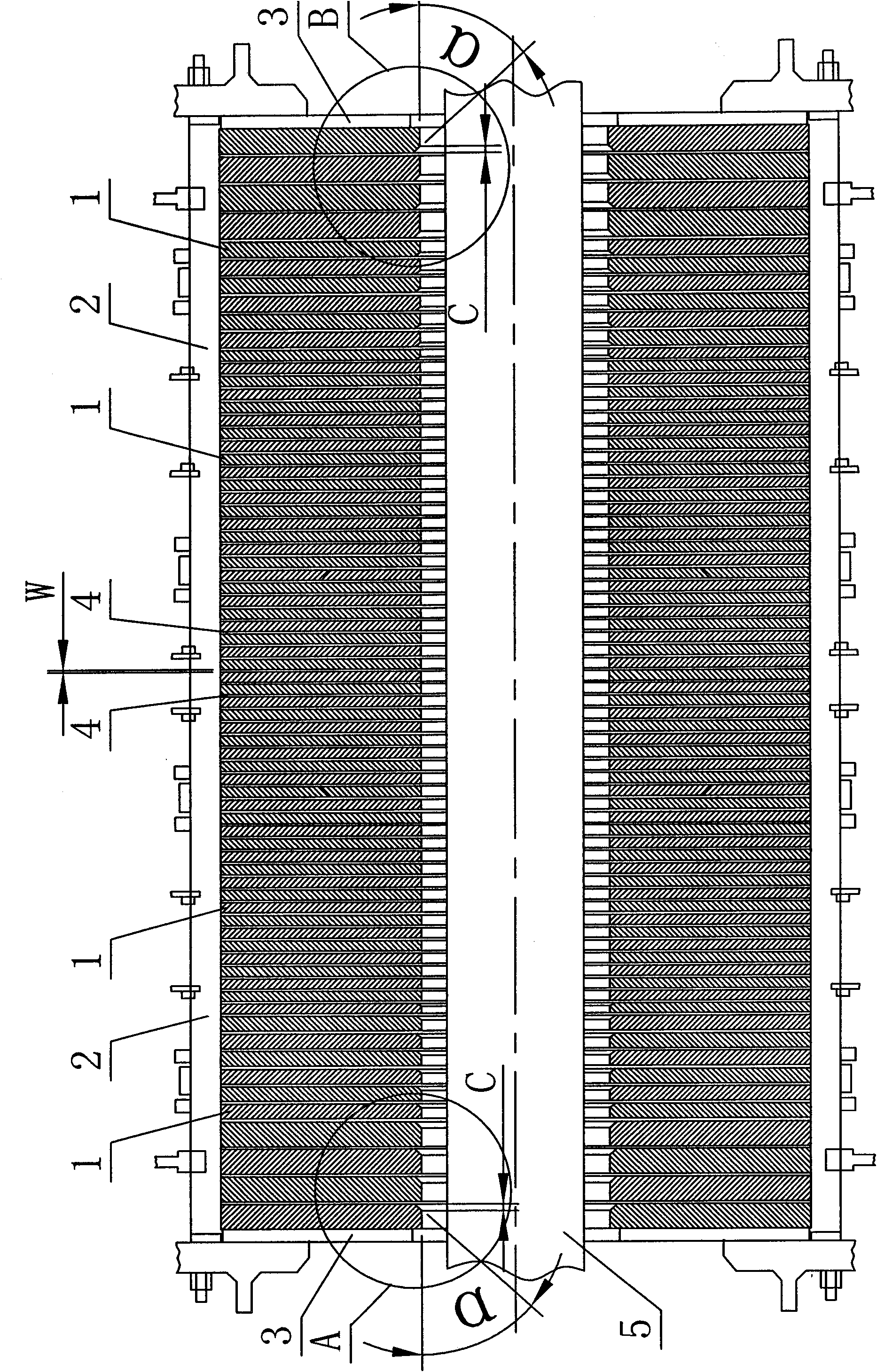
[0008] Specific implementation mode one: as Figure 1~5 , Figure 6a~6c As shown, a large-scale air-cooled turbogenerator stator that can improve the ventilation and cooling effect described in this embodiment includes two pressure plates 3, at least two positioning ribs 2 and a plurality of iron core segments 1, and each iron core segment 1 The outline shape is circular, a plurality of iron core segments 1 are coaxially arranged to form a stator main body and the stator main body is placed between two pressure plates 3, and the at least two positioning ribs 2 are evenly distributed in the axial direction on the On the outer surface of the stator main body, the at least two positioning ribs 2 form an air gap 4 between every two adjacent iron core segments 1, the air gap 4 is a radial ventilation groove and the radial ventilation groove The width W of the at least two positioning ribs 2 is 6 mm to 8 mm, and one end of the at least two positioning ribs 2 is fixedly connected to...

specific Embodiment approach 2

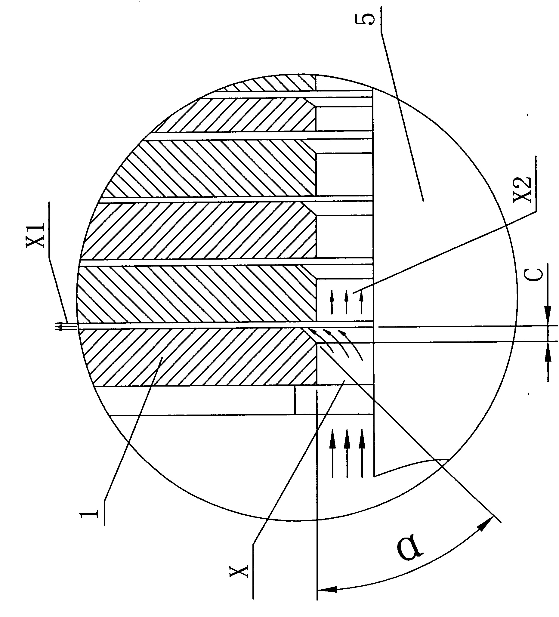
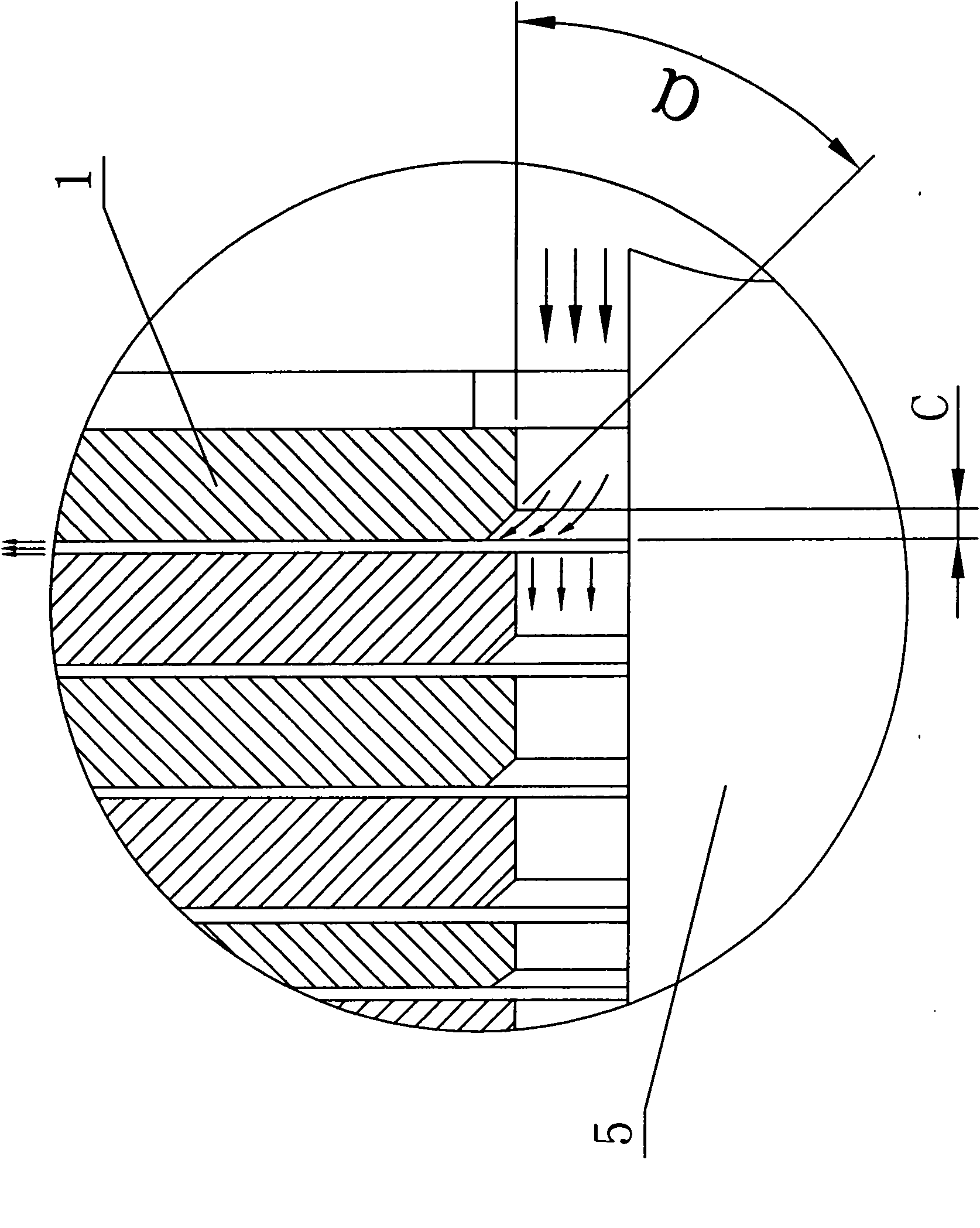
[0009] Specific implementation mode two: as figure 1 As shown, the iron core segments 1 located at both ends of the stator main body in this embodiment refer to ten to fifteen iron core segments 1 located at both ends of the stator main body, that is, from the outermost ends of the two ends of the stator main body to the The above-mentioned chamfers are all formed on the ten to fifteen iron core segments 1 of the inner number. The core sections of the 200MW air-cooled turbogenerator are not equally spaced in the axial direction, and the thickness of the iron core section from the end is relatively thick, so the electromagnetic loss generated by each iron core section at the end is larger than that of the middle section. When the width of the ventilation ditch is constant, The ability of the fluid in the ventilation ditch to take away the heat of the heating element is certain, causing the iron core temperature of the end section to be higher than that of the middle section. R...

specific Embodiment approach 3

[0010] Embodiment 3: The chamfer α in this embodiment is 65°. Other components and connections are the same as those in the first embodiment.


PUM


Abstract

The invention discloses a large air-cooling steam turbo generator stator capable of improving aeration-cooling effect and relates to a large air-cooling steam turbo generator stator. For reducing the maximum temperature rise of an air-cooling steam turbo generator stator bar, the invention adopts the technical points that: an orifice of inner bores of iron core sections which are positioned at the two ends of a stator main body is provided with a chamfer angle (alpha) of between 60 and 75 DEG, the orifice is an axial opening close to one side of an axial midperpendicular plane of the stator main body, and the depth (C) of the chamfer angle is 6 to 12mm. The heat radiating efficiency of a motor cooling system can be effectively improved due to the adoption of the generator stator structure provided by the invention; and under the condition of a given inlet and fixed outlet pressure, when a chamber angle scheme is adopted, experiments prove that the maximum temperature is 3 DEG C lower than that of the conventional scheme after the temperature of the generator stator structure is solved, so the temperature of the hottest section of a motor is effectively reduced, and the whole temperature area of the motor is uniformized.

Description

technical field [0001] The invention relates to a large-scale air-cooled turbogenerator stator, which belongs to the technical field of large-scale air-cooled turbogenerator cooling. Background technique [0002] The improvement of the turbo-generator capacity is mainly achieved by increasing the linear size of the generator and increasing the electromagnetic load. However, in practice, due to the limitations of the stator transportation size, rotor forgings and rotor deflection, the capacity increase of the turbogenerator is mainly realized by increasing the electromagnetic load. However, increasing the wire load will increase the copper loss of the wire rod at the same time, and the temperature of the coil will rise, even exceeding the allowable temperature rise. For this reason, more effective cooling technology must be adopted to increase its heat dissipation intensity, so as to control the temperature rise of each part of the turbogenerator within the allowable range, ...

Claims


Application Information

Patent Timeline
Patent Type & Authority Applications(China)
IPC IPC(8): H02K1/20
Inventor 李伟力管春伟李勇
Owner HARBIN UNIV OF SCI & TECH
Why Eureka
Try Eureka