

Heat sink, assembly, and method of making
a technology of heat sink and heat sink body, which is applied in the direction of lighting and heating apparatus, semiconductor/solid-state device details, and laminated elements, etc., can solve the problems of liquid cooling as a last resort, the acceptable cost of heat dissipating devices has remained constant or, in many cases, dropped, etc., to reduce the overall system size and cost, and the effect of dissipating large amounts of power
- Summary
- Abstract
- Description
- Claims
- Application Information
AI Technical Summary
Benefits of technology
Problems solved by technology
Method used
Image

Examples
Embodiment Construction
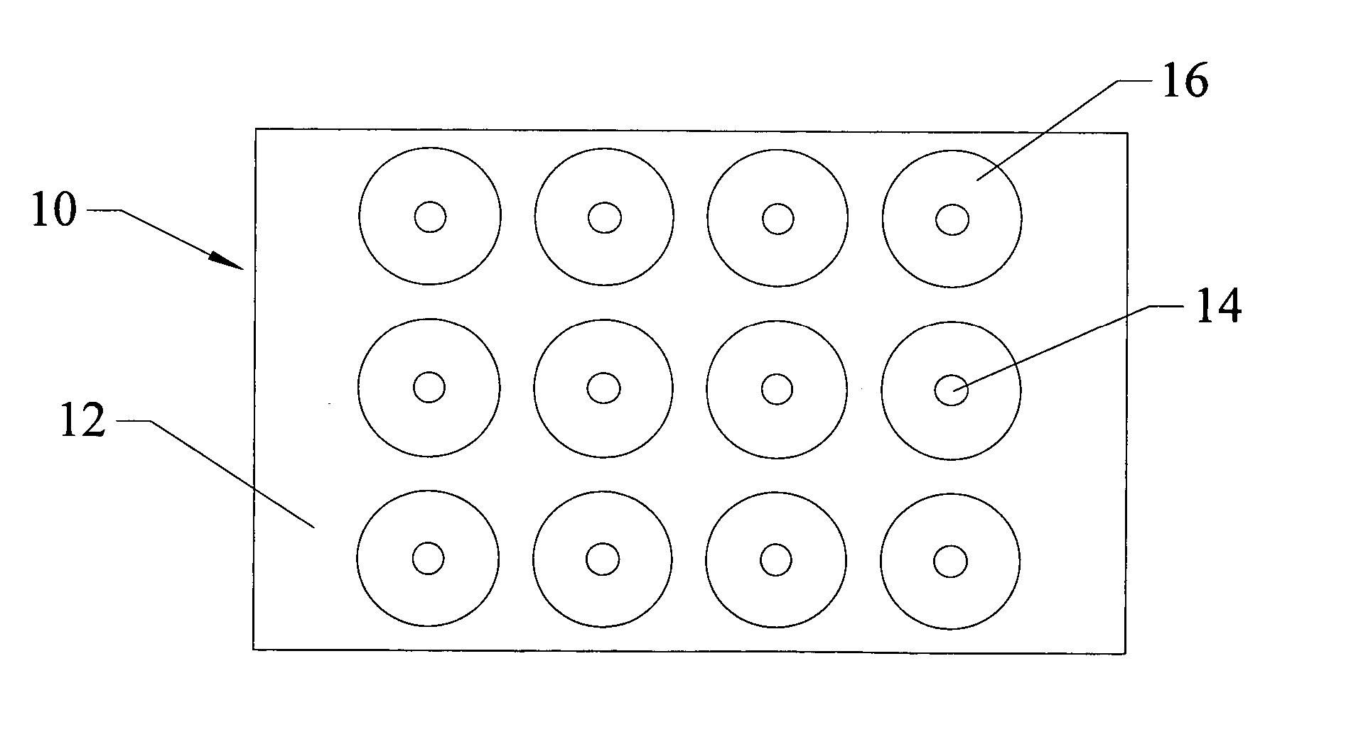
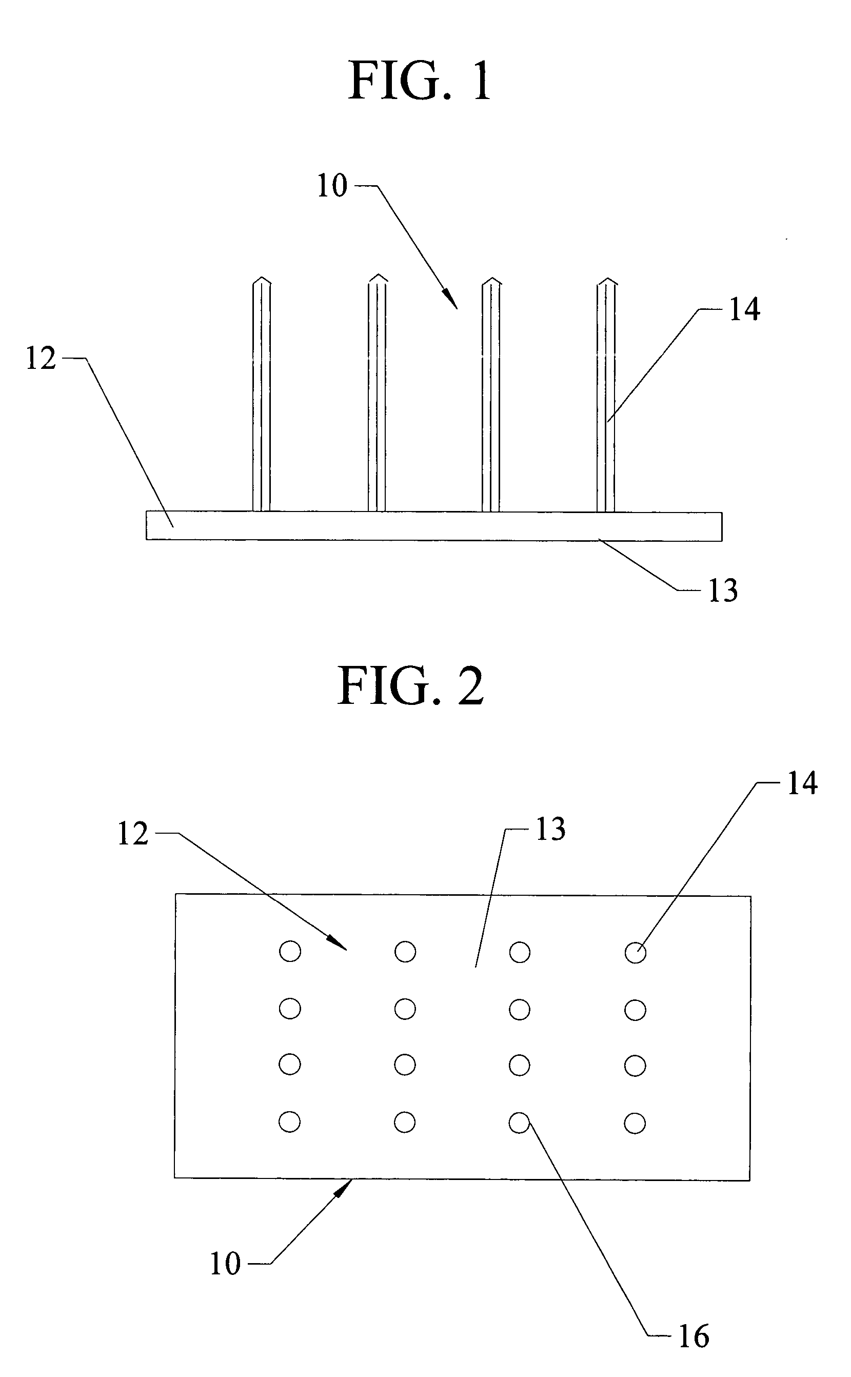
[0050] Referring first to FIGS. 1 and 2, one embodiment of the heat sink 10 of the present invention is shown. The heat sink 10 includes a base plate 12 and a plurality of heat pipes 14 that extend from the top surface 15 of the base plate 12. The base plate 12 has a bottom surface 13 that is dimensioned and shaped to promote good thermal contact with the heat source (not shown). The base plate 12 is manufactured of a material, such as copper or aluminum, that has relatively good thermal conductivity, and should be of sufficient thickness to efficiently spread the heat from a heat source (not shown) disposed upon its bottom surface 13 to the heat pipes 14 extending from its top surface 15. In many of the embodiments shown herein, the base plate 12 is portrayed as a substantially solid rectangular plate. However, it is recognized that base plates 12 having different shapes and / or cross sections may be utilized and the present invention should not be viewed as being limited to heat si...
PUM
 Abstract
Description
Claims
Application Information