Speed-changing device

a technology of speed-changing devices and mechanical units, which is applied in the direction of fluid gearings, transportation and packaging, gearing, etc., can solve the problems of poor efficiency, disadvantageous economic efficiency, and deterioration of the transmission efficiency of mechanical units, so as to reduce the capacity of pump-motors, increase efficiency, and increase the effect of capacity

Active Publication Date: 2006-09-28
KOMATSU LTD
View PDF11 Cites 26 Cited by
  • Summary
  • Abstract
  • Description
  • Claims
  • Application Information

AI Technical Summary

Benefits of technology

[0025] It is preferable that at least either the first pump-motor or the second pump-motor is constituted by a plurality of pump-motors. With this arrangement, only one pump-motor can be driven during an operation which requires small capacity just after switching from a direct mode for transmitting power only by the mechanical unit to a hydraulic mechanical transmission mode (HMT mode) for transmitting power by both the hydraulic unit and the mechanical unit. And, after switching to an operation which requires high capacity, two pump-motors are brought into operation. This leads to further increased efficiency.
[0026] In this case, at least one of the plurality of pump-motors which constitute the first or second pump motor is connected to the planetary gear mechanism with a speed reduction ratio different from those of other pump-motors. Thereby, the speed range covered by each pump-motor can be varied, which can reduce the capacity of the pump-motors.
[0027] Preferably, some of the plurality of pump-motors which constitute the first or second pump motor are each replaced with a generator-motor and, under a predetermined condition, motive power is transmitted by electric-mechanical transmission instead of hydraulic-mechanical transmission. Thereby, further improved efficiency can be achieved by making effective use of the merits of a low-cost hydraulic power transmission system having high power density and an electric power transmission system having good efficiency.
[0028] In each of the above inventions, it is preferable to use a unidirectional rotation type pump-motor as the first pump-motor and to use a selector valve for switching a flow of pressure oil toward the unidirectional rotation type pump-motor so as to be constantly directed in a specified direction. The effective use of the inexpensive unidirectional rotation type pump-motor leads to a reduction in the cost of the whole system.
[0029] In the invention, it is preferable to provide controlling means for controlling the switching mechanism so as to establish, at the time of switching operation performed by the switching mechanism, a vehicle speed region which brings the rotation of the second pump-motor to a stop. Thereby, all energy passes through the mechanical unit at the time of switching so that the capacity of the first pump-motor becomes zero and no torque is imposed on the first pump-motor. Therefore, no energy flows in the switching section of the input / output shafts of the first pump-motor, which eliminates the need for a slipping clutch or the like and, in consequence, facilitates the switching.
[0030] Herein, the vehicle speed region which brings the rotation of the second pump-motor to a stop may be no less than a maximum torque point of the engine and no more than a rated torque point. Thereby, the rotation of the second pump-motor can be stopped over a wide range of engine rotating speeds so that switching can be more smoothly carried out and the transmission efficiency can be highly improved because transmission can be performed only by the mechanical unit over a wide range of vehicle speeds.

Problems solved by technology

As just discussed, when hydraulic power flows in the reverse direction, a flow of large energy occurs in each element, causing poor efficiency.
This entails a need for a larger planetary gear mechanism, which is disadvantageous in economical efficiency.
The technique disclosed in this publication, however, is complicated in the structure of the planetary gear mechanism and inevitably involves a multiplicity of gears which do not participate in energy transmission, increasing idling losses with the result that the transmission efficiency of the mechanical unit deteriorates.
Furthermore, the technique disclosed in this publication has revealed such a drawback that since it is designed to shift gears by switching the transmission path between the planetary gear mechanism and the output shaft through engagement / disengagement of clutches, a so-called torque shortage (i.e., a momentary drop in the torque of the output shaft) or a gear change shock will occur if the timing of clutch engagement / disengagement is bad.

Method used


Image

  • Speed-changing device
  • Speed-changing device
  • Speed-changing device

Examples


first embodiment

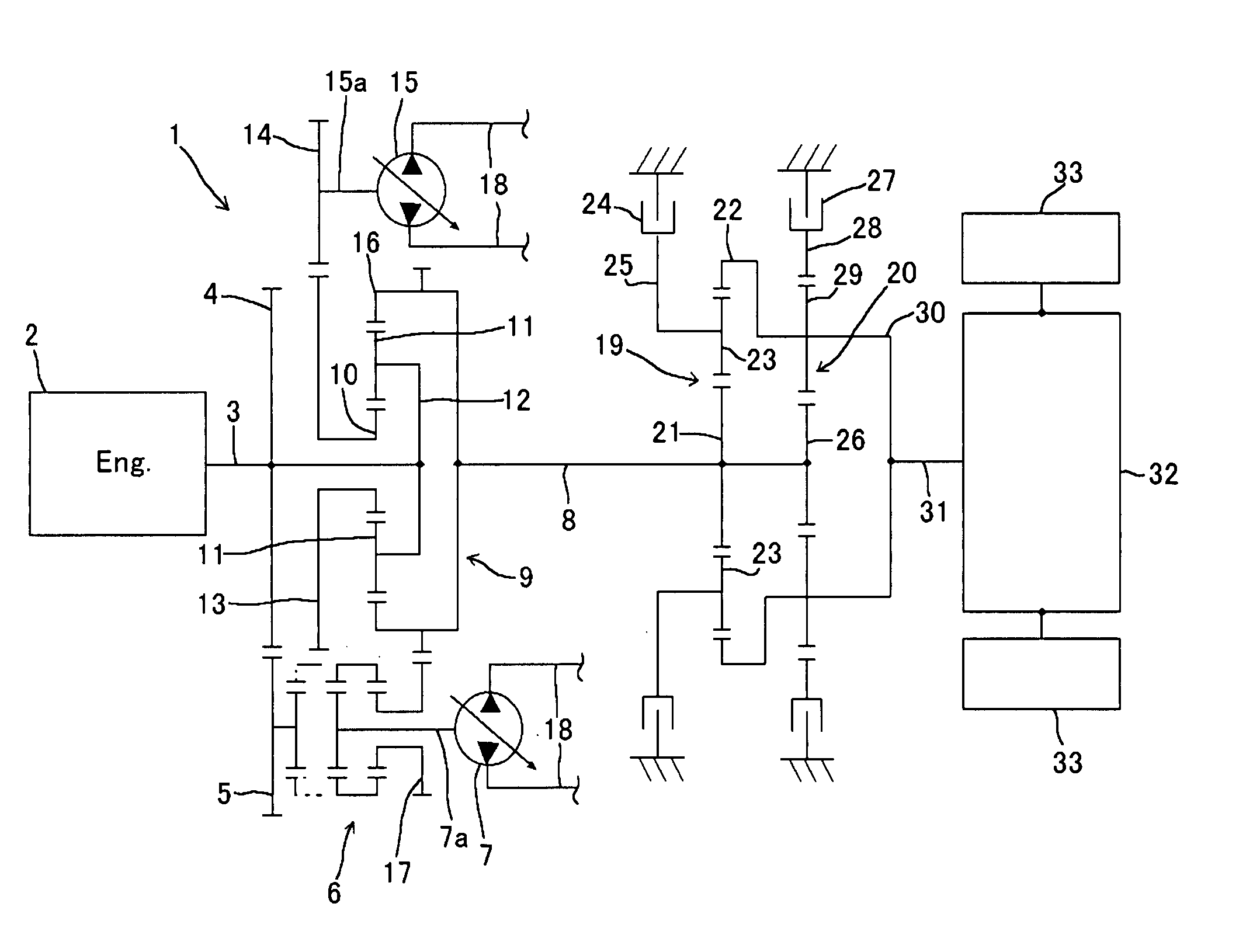
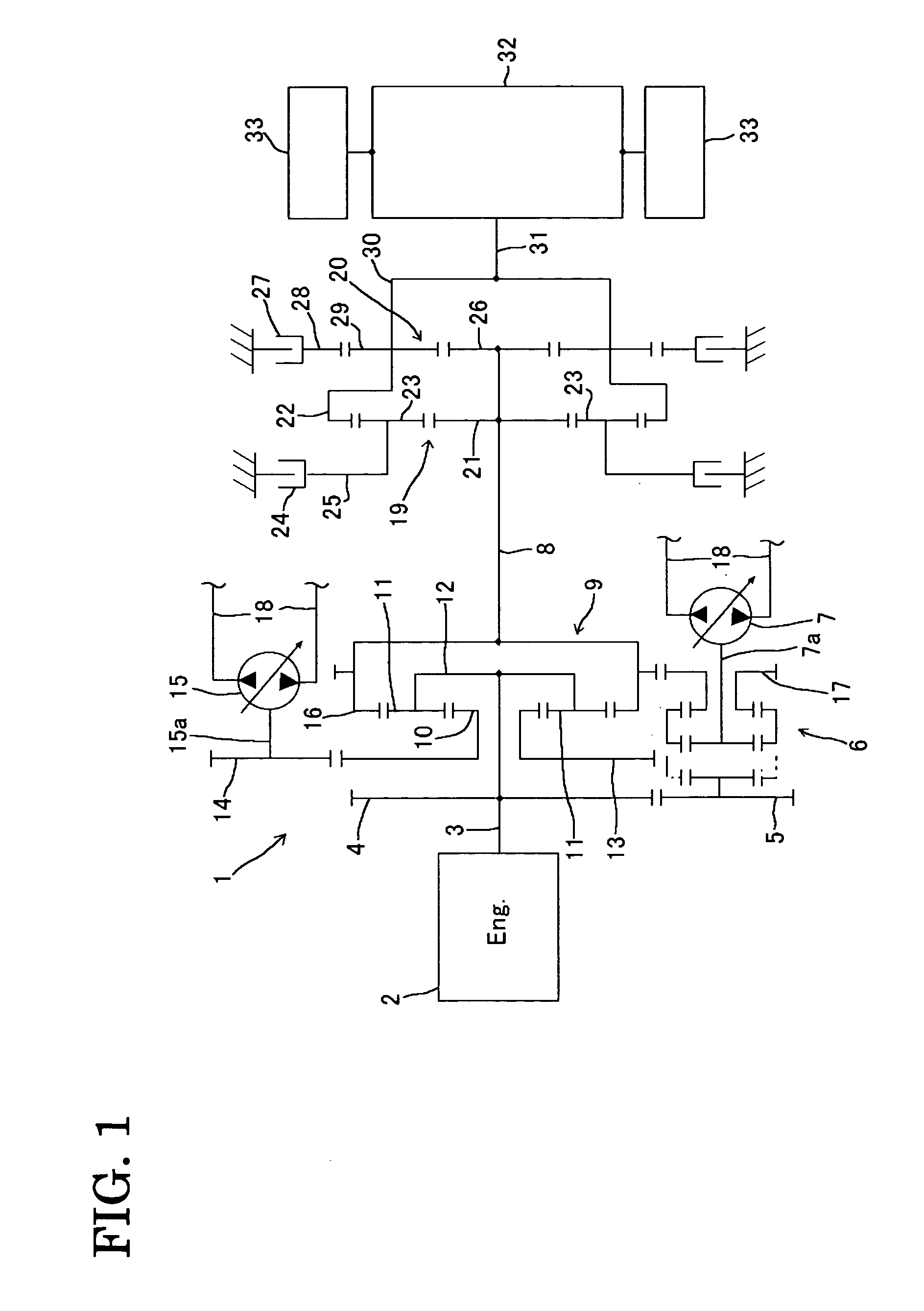
[0058]FIG. 1 is a schematic structural diagram of a transmission constructed according to a first embodiment of the invention. While the invention is applied to the transmission of a track-type vehicle such as bulldozers in this embodiment, it is obvious that the invention is not limited to this application.

[0059] In a transmission 1 constructed according to this embodiment, a first gear 4 is secured to an input shaft 3 to which motive power from an engine 2 is input. A second gear 5 meshes with the first gear 4 such that the second gear 5 can be coupled to a shaft 7a of a first pump-motor 7 through a synchromesh mechanism 6. The synchromesh mechanism 6 is situated between the second gear 5 and a fifth gear 17 (described later), and upon switching of the synchromesh mechanism 6, the rotation of the shaft 7a is selectively brought into synchronization with the rotation of the second gear 5 or the rotation of the fifth gear 17.

[0060] Disposed between the input shaft 3 and an interme...

second embodiment

[0086]FIG. 8 shows a schematic structural diagram of a transmission according to a second embodiment of the invention. The transmission 1A of the second embodiment does not basically differ from that of the first embodiment except the structure of a speed-change planetary gear mechanism 9A. Therefore, the parts of the second embodiment which correspond to those of the first embodiment are identified by the same reference numerals as of the first embodiment and a detailed description of them is skipped herein (the same applies to each of the following embodiments).

[0087] In the speed-change planetary gear mechanism 9A of the second embodiment, the sun gear 10 is rotatably borne by the input shaft 3 and the ring gear 16 is fixed to the input shaft 3. The planetary carrier 12 for bearing the planetary gears 11 is fixed to the intermediate output shaft 8. Meshing with the outer circumference of the planetary carrier 12 is the fifth gear 17.

[0088] In the transmission 1A of the second e...

third embodiment

[0090]FIG. 9 shows a schematic structural diagram of a transmission according to a third embodiment of the invention.

[0091] In a speed-change planetary gear mechanism 9B according to the third embodiment, the sun gear 10 is fixed to the input shaft 3 and the ring gear 16 is fixed to the intermediate output shaft 8. The fifth gear 17 meshes with the outer circumference of the ring gear 16. The planetary carrier 12 for bearing the planetary gears 11 is integrally coupled to the third gear 13.

[0092] In the transmission 1B of the third embodiment, if the shaft 7a of the first pump-motor 7 is coupled to the second gear 5 side while the rotating speed of the intermediate output shaft 8 is on the speed-up side, the motive power of the engine 2 is input to the sun gear 10 whereas the motive power of the second pump-motor 15 serving as a motor is input to the planetary gear 12, so that these motive powers are combined and output as the rotary motion of the ring gear 16 to be transmitted to...


PUM


Abstract

A transmission is provided which has a very compact system configuration and is capable of exerting high energy efficiency over all speed regions from a low speed region to a high speed region, while providing improved operability free from a torque shortage. To this end, the transmission has an input shaft 3, an intermediate output shaft 8, a planetary gear mechanism 9, a first pump-motor 7, and a second pump-motor 15 connected to the first pump-motor 7, the input shaft 3 being coupled to a first element (planetary carrier 12) of the planetary gear mechanism 9, the second pump-motor 15 being coupled to a second element (sun gear 19) of the planetary gear mechanism 9, the intermediate output shaft 8 being coupled to a third element (ring gear 16) of the planetary gear mechanism 9, and the transmission further comprising a switching mechanism (synchromesh mechanism 6) for selectively coupling the first pump-motor 7 to either the input shaft 3 or the intermediate output shaft 8.

Description

TECHNICAL FIELD [0001] The present invention relates to a hydraulic-mechanical or electro-mechanical transmission having a planetary gear mechanism in combination with pump-motors or generator-motors. BACKGROUND ART [0002] There are conventionally known, as hydraulic transmissions, (i) pure hydraulic transmissions (e.g., hydrostatic transmissions (HST)) which convert all input power supplied from an engine into oil pressure and transmit it and (ii) hydro-mechanical (power-split type) transmissions (HMT) which hydraulically transmit part of input power while mechanically transmitting the remaining part. The latter transmissions (HMT) have the advantage of achieving higher efficiency than the former transmissions (HST) since they convert only part of mechanical power into hydraulic power and the transmission efficiency of mechanical power is high. For this reason, the hydro-mechanical transmissions are said to be ideal transmissions for vehicles subjected to significant load fluctuati...

Claims


Application Information

Patent Timeline
Patent Type & Authority Applications(United States)
IPC IPC(8): F16H47/04B60K6/365B60K6/485B60W10/10B60W20/00F16H61/00
CPCF16H47/04F16H2037/0866F16H2037/088F16H3/728
Inventor HIRAKI, HIKOSABUROKUSE, TAKASHIOKADA, TOSHIKAZU
Owner KOMATSU LTD
Why Eureka
Try Eureka