Cooled components with conical cooling passages

a cooling passage and conical technology, applied in the field of components, can solve the problems of negative diffuser effect, unfavorable passage divergence within the range normally realized in film-cooling passages, etc., and achieve the effect of improving wetting of the component surface and high production accuracy

Inactive Publication Date: 2005-08-02
ANSALDO ENERGIA IP UK LTD
View PDF20 Cites 24 Cited by
  • Summary
  • Abstract
  • Description
  • Claims
  • Application Information

AI Technical Summary

Benefits of technology

[0012]It remains to be stated that a multiplicity of cooling passages, the diameter of which ranges typically in the order of magnitude from a few tenths of a millimeter up to slightly more than 1 millimeter, are to be made in a component to be cooled, and that, especially if a defined diffuser effect is aimed at, a very high production accuracy is to be demanded. It furthermore remains to be stated that the diffuser geometry in the case of pure film cooling has considerable advantages, in which case the better wetting of the component surface with the cooling medium could be mentioned in the first place. It also remains to be stated that the better tangential application of the cooling medium, as outlined above, is unable to develop any significant effect in the immediate vicinity of the stagnation points of the hot-gas incident flow, but rather that the considerable task at these locations is to ensure that the cooling-medium mass flow, at a small pressure ratio, deviates as little as possible from the design mass flow.

Problems solved by technology

On the other hand, a passage divergence within the range which is normally realized in film-cooling passages is already unfavorable, since in the present case a pronounced diffuser effect tends to be negative.

Method used


Image

  • Cooled components with conical cooling passages
  • Cooled components with conical cooling passages
  • Cooled components with conical cooling passages

Examples


Embodiment Construction

[0034]Referring now to the drawings, wherein like reference numerals designate identical or corresponding parts throughout the several views, the invention is illustrated with reference to a cooled turbine blade. However, this is not to be understood in a restrictive sense, since the person skilled in the art, instead of applying the invention to a component around which hot gas flows, can readily apply it to components to which hot gas is admitted only on one side, such as, for example, combustion-chamber segments.

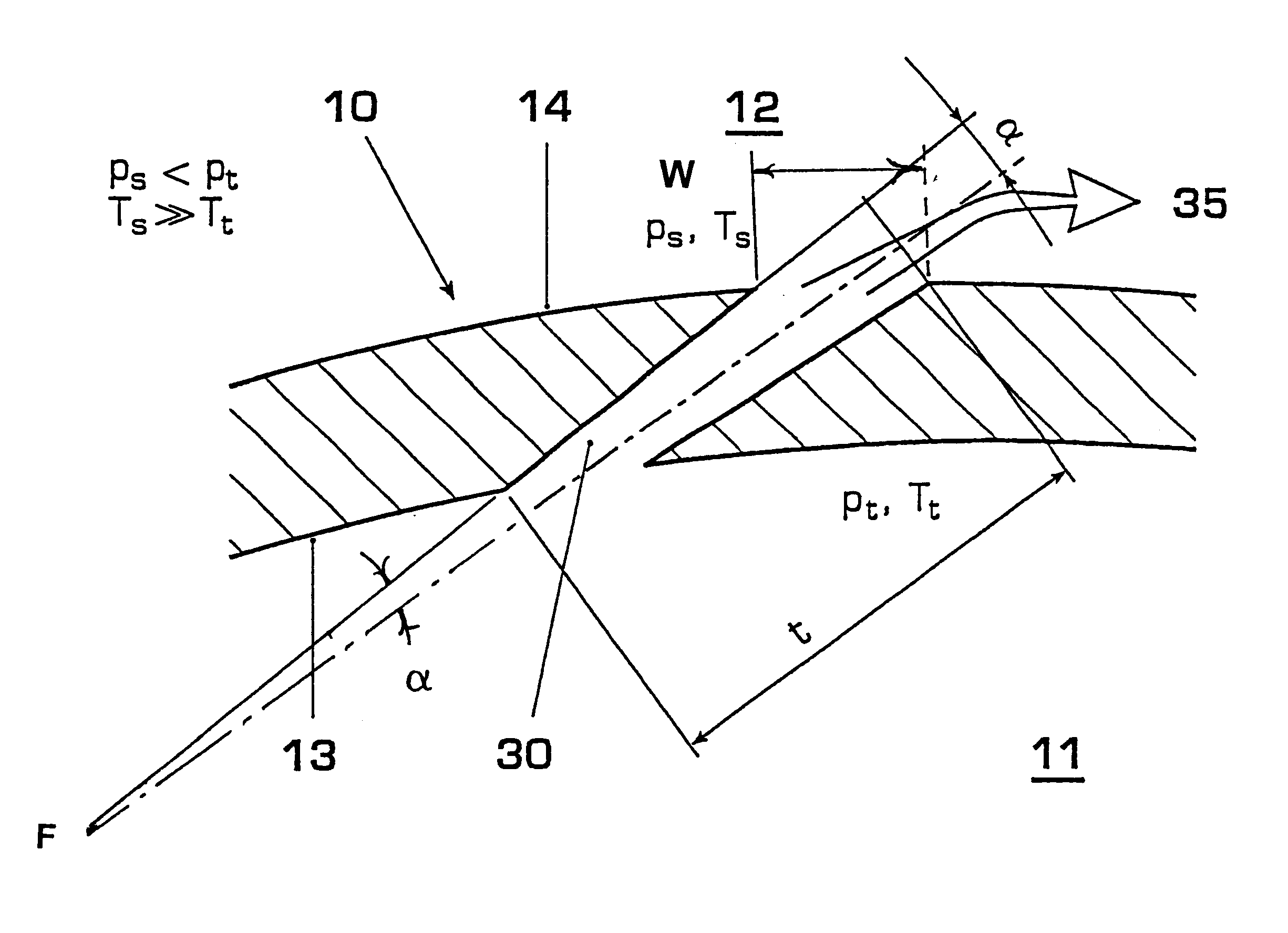
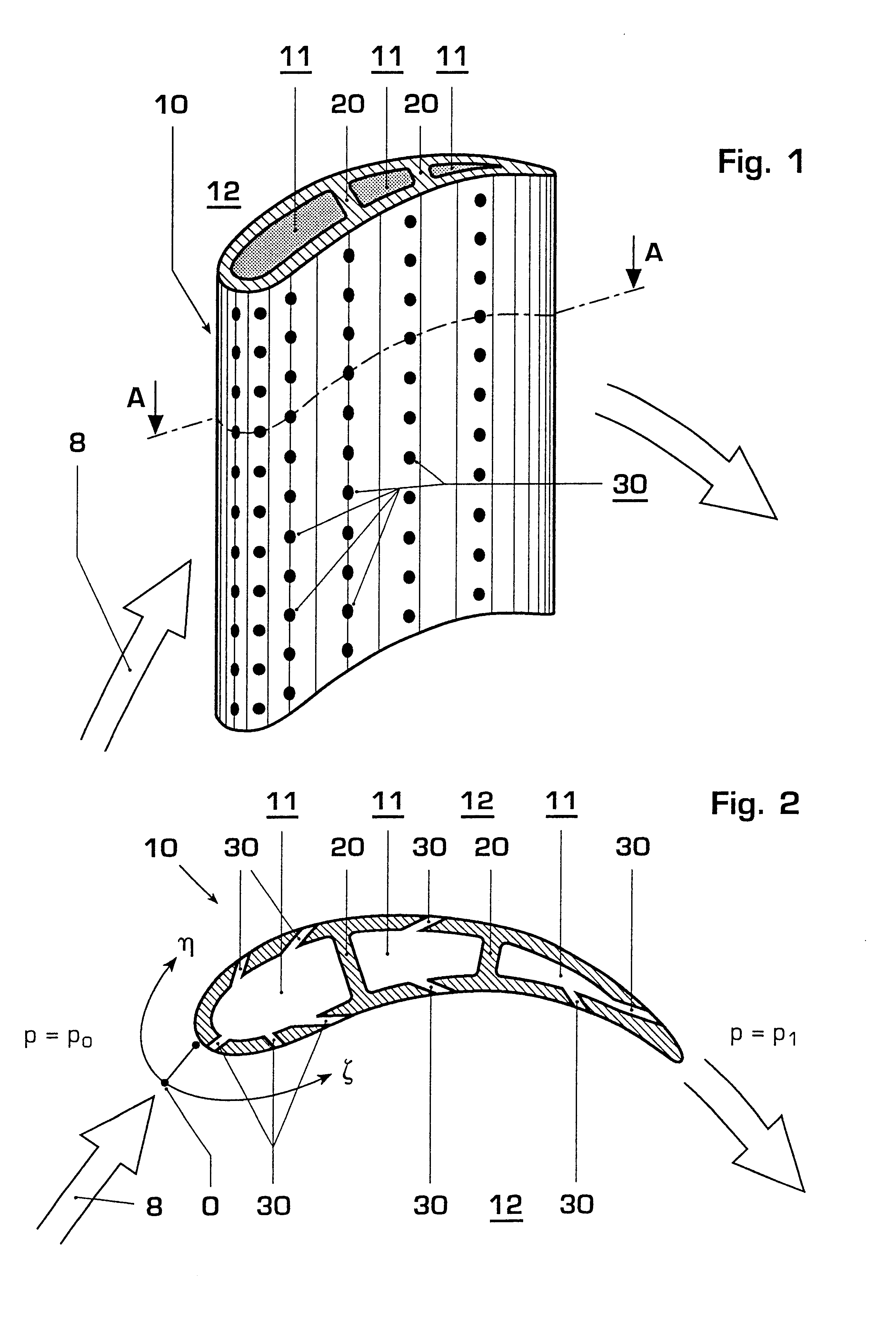
[0035]FIG. 1 shows an example for the configuration of a cooled turbine blade 10, which is subjected to flow in the direction of the arrows. The blade contains cavities 11, which are separated from one another by webs 20. The discharge openings of the cooling passages 30 can be seen on the outside of the blade. Cooling medium is to discharge from the cavities 11 through these discharge openings and if possible flow off along the blade surface and thus insulate the blade f...


PUM

PropertyMeasurementUnit
diameteraaaaaaaaaa
opening half angleaaaaaaaaaa
heataaaaaaaaaa

Abstract

A thermally highly loaded machine component (10), which is protected from overheating by film cooling, is provided with conical cooling passages (30) of circular cross section. The cooling passages are designed so as to be divergent from the cold-gas side (13) toward the hot-gas side. The conical cooling passages, as compared with cylindrical passages with regard to the mass flow of cooling medium (35) fed through the cooling passages, are substantially less dependent on the pressure ratio between the cold-gas side (13) and hot-gas side (14) of the component. The straight conical cooling passages of round cross section throughout may be produced in a very simple manner by laser drilling, with a convergent cutting beam being used for the machining.

Description

BACKGROUND OF THE INVENTION[0001]1. Field of the Invention[0002]The invention relates to a component which can be subjected to high thermal loading and to which a hot-gas flow is admitted during operation, which component has at least one hot-gas side exposed to the hot-gas flow and a cold-gas side not exposed to the hot-gas flow, in which component passages are made, which passages connect the hot-gas side and the cold-gas side in such a way that a cooling medium flows from the cold-gas side to the hot-gas side, which cooling medium, when passing through a passage, absorbs heat from the component and draws it off to the hot-gas side, at least one of the cooling passages having an essentially circular cross section over its entire length, which cross section increases continuously from the cold-gas side to the hot-gas side, an opening half angle being enclosed, so that the at least one passage appears frustoconical.[0003]2. Discussion of Background[0004]In modern technology it is of...

Claims


Application Information

Patent Timeline
Patent Type & Authority Patents(United States)
IPC IPC(8): B23K26/00B23K26/38F01D5/18
CPCB23K26/388F01D5/186Y10T29/49341F05D2250/232B23K26/389
Inventor FERBER, JORGENWEIGAND, BERNHARD
Owner ANSALDO ENERGIA IP UK LTD
Why Eureka
Try Eureka