Infrared ruby lamp tube

A ruby, infrared technology, applied in the direction of heating element material, heating element shape, etc., can solve problems such as human body injury, and achieve the effect of enhancing transmittance and thermal effect

Inactive Publication Date: 2010-12-15
王明海
View PDF0 Cites 1 Cited by
  • Summary
  • Abstract
  • Description
  • Claims
  • Application Information

AI Technical Summary

Problems solved by technology

The infrared lamp with this structure not only irradiates the required infrared light, but also irradiates unnecessary ultraviolet light, and ultraviolet light is harmful to the human body.

Method used


Image

  • Infrared ruby lamp tube
  • Infrared ruby lamp tube
  • Infrared ruby lamp tube

Examples


Embodiment Construction

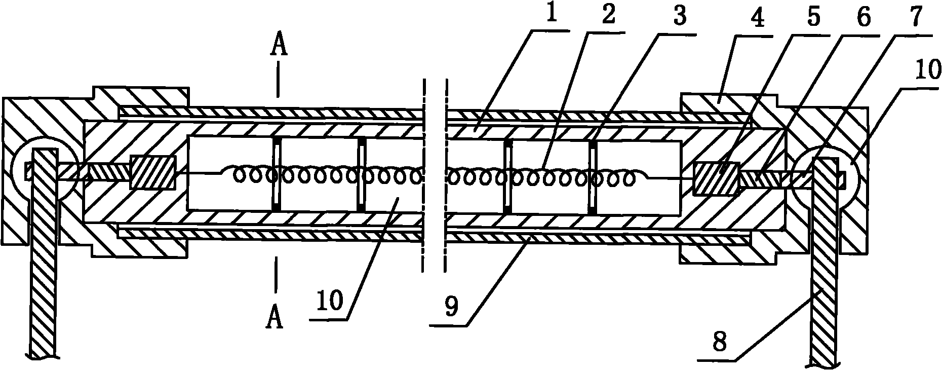
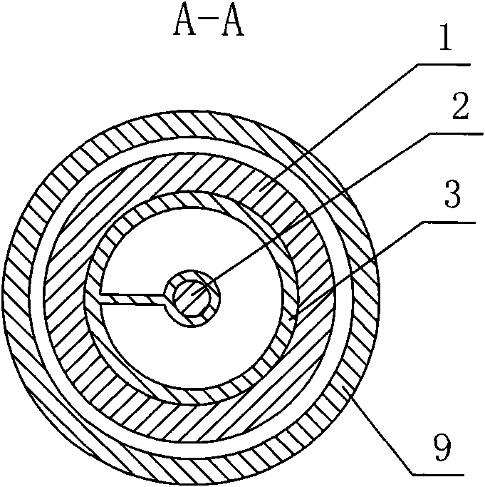
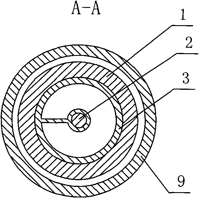
[0008] Such as figure 1 , 2 As shown, it is an infrared ruby ​​lamp tube, which includes a transparent glass tube 1 with both ends sealed. An inert gas 10 is arranged in the glass tube 1. The two ends of the glass tube 1 are respectively provided with insulating mounting porcelain seats 4, and each insulating mounting porcelain seat 4 Through-holes 10 are respectively provided on them. A ruby ​​glass tube 9 is sleeved outside the glass tube, and the two ends of the ruby ​​glass tube 9 are respectively arranged in the insulating mounting porcelain seat 4.

[0009] A tungsten wire 2 is arranged inside the glass tube 1, and at least two bracket rings 3 are connected to the tungsten wire 2 at intervals. The two ends of the tungsten wire 2 are respectively spot-welded with the molybdenum sheet 5, the other end of each molybdenum sheet 5 is respectively spot-welded with the molybdenum rod 6, the other end of each molybdenum rod 6 is spot-welded with the stainless steel terminal 7,...


PUM


Abstract

The invention discloses an infrared ruby lamp tube and relates to the technical field of industrial warming, drying or heating equipment, and the infrared ruby lamp tube comprises a transparent glass tube, the two ends of which are sealed, the glass tube is filled with inert gas, and the two ends of the glass tube are respectively provided with an insulating installation ceramic seat which is provided with a through hole; the glass tube is internally provided with a tungsten wire, and at least two bracket rings are connected on the tungsten wire at an interval; two ends of the tungsten wire are respectively connected with molybdenum sheets, the other end of each molybdenum sheet is connected with a stainless steel terminal through a molybdenum rod, the other end of each stainless steel terminal is arranged in the through hole, the other end of the stainless steel terminal is connected with a wire, a ruby glass tube is sleeved and arranged outside the glass tube, and two ends of the ruby glass tube are respectively arranged in the insulating installation ceramic seats. By adopting the design, the transmissivity and the thermal effect of short-wave infrared ray are enhanced greatly, and moreover, ultraviolet rays harmful to people and dazzling visible light are intercepted effectively.

Description

technical field [0001] The invention relates to the technical field of industrial heating, drying or heating equipment. Background technique [0002] Ordinary infrared lamp tubes include transparent glass tubes with both ends sealed. Inert gas is set in the glass tubes. Insulation mounting porcelain seats are respectively set at both ends of the glass tubes, and through holes are respectively set on each insulation mounting porcelain seat; The tungsten wire is connected with at least two support rings at intervals; the two ends of the tungsten wire are respectively connected to molybdenum sheets, and the other end of each molybdenum sheet is connected to a stainless steel terminal through a molybdenum rod, and the other end of each stainless steel terminal is respectively set In the through hole, the other end of each stainless steel terminal is respectively connected with a wire. The infrared lamp tube of this structure not only irradiates the required infrared light, but ...

Claims


Application Information

Patent Timeline
Patent Type & Authority Applications(China)
IPC IPC(8): H05B3/44H05B3/10
Inventor 王明海
Owner 王明海
Why Eureka
Try Eureka