
Plate rolling mill and plate rolling method

A flat rolling mill and flat rolling technology, applied in the direction of rolling mill control device, metal rolling stand, metal rolling stand, etc., can solve the problem of inability to suppress the change of work roll offset and the inability to suppress the work roll offset , changes and other issues

Active Publication Date: 2010-12-15
NIPPON STEEL CORP
View PDF11 Cites 9 Cited by
  • Summary
  • Abstract
  • Description
  • Claims
  • Application Information

AI Technical Summary

Problems solved by technology

[0004] However, the rolling mill described in Japanese Patent Application Laid-Open No. 05-038504 has a structure in which only the work roll chocks are pressed, so there is a problem in that it is impossible to suppress the friction between the work roll chocks and the work rolls. The problem of the change of the work roll offset caused by the looseness of the work roll bearing
[0016] However, the external force generated by these pressing devices is applied through the chock, and therefore, similar to JP 05-038504 A, there is a problem that the looseness of the work roll bearing existing between the work roll chock and the work roll cannot be suppressed. The problem of the change of the work roll offset

Method used


Image

  • Plate rolling mill and plate rolling method
  • Plate rolling mill and plate rolling method
  • Plate rolling mill and plate rolling method

Examples


Embodiment Construction

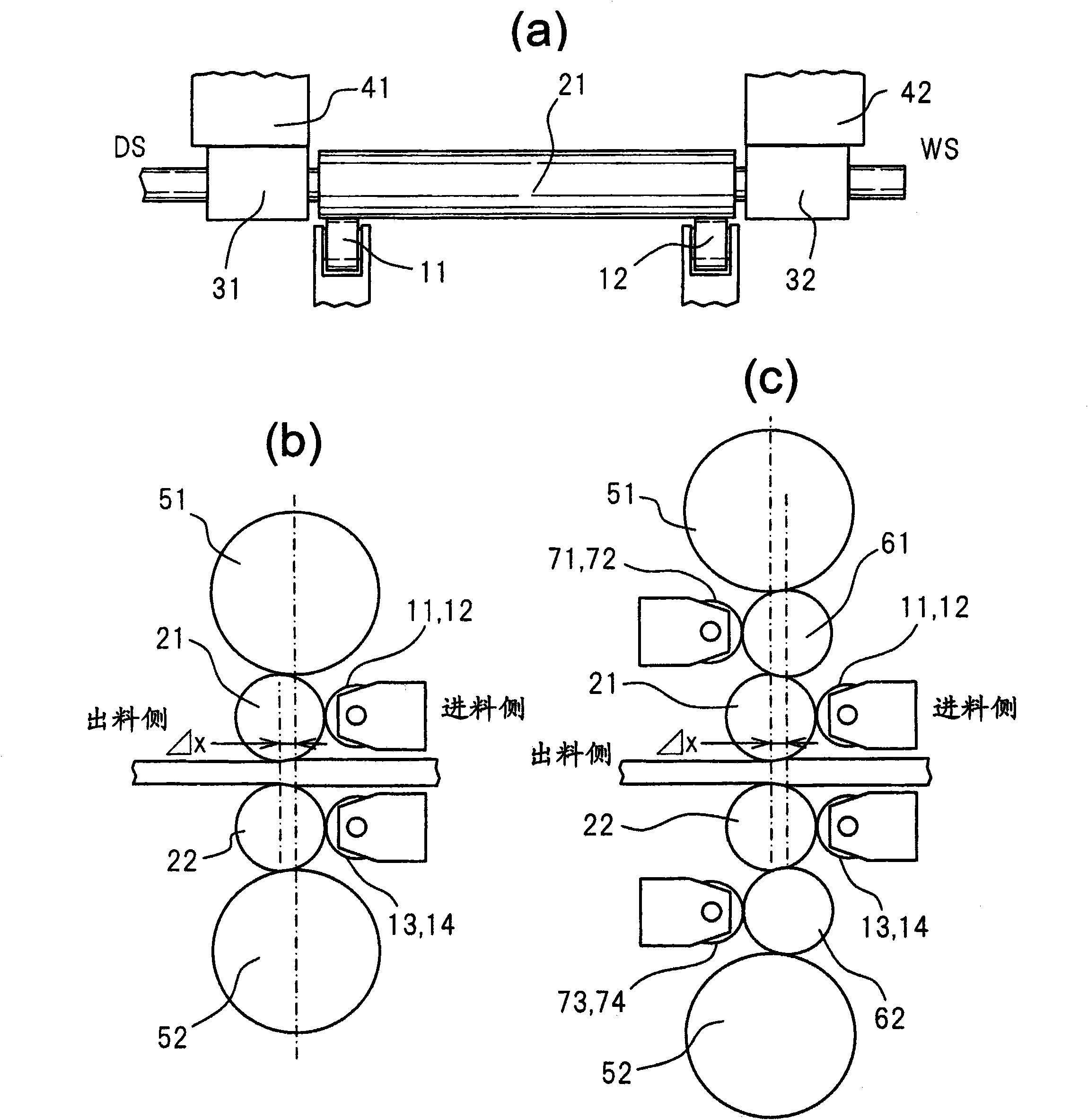
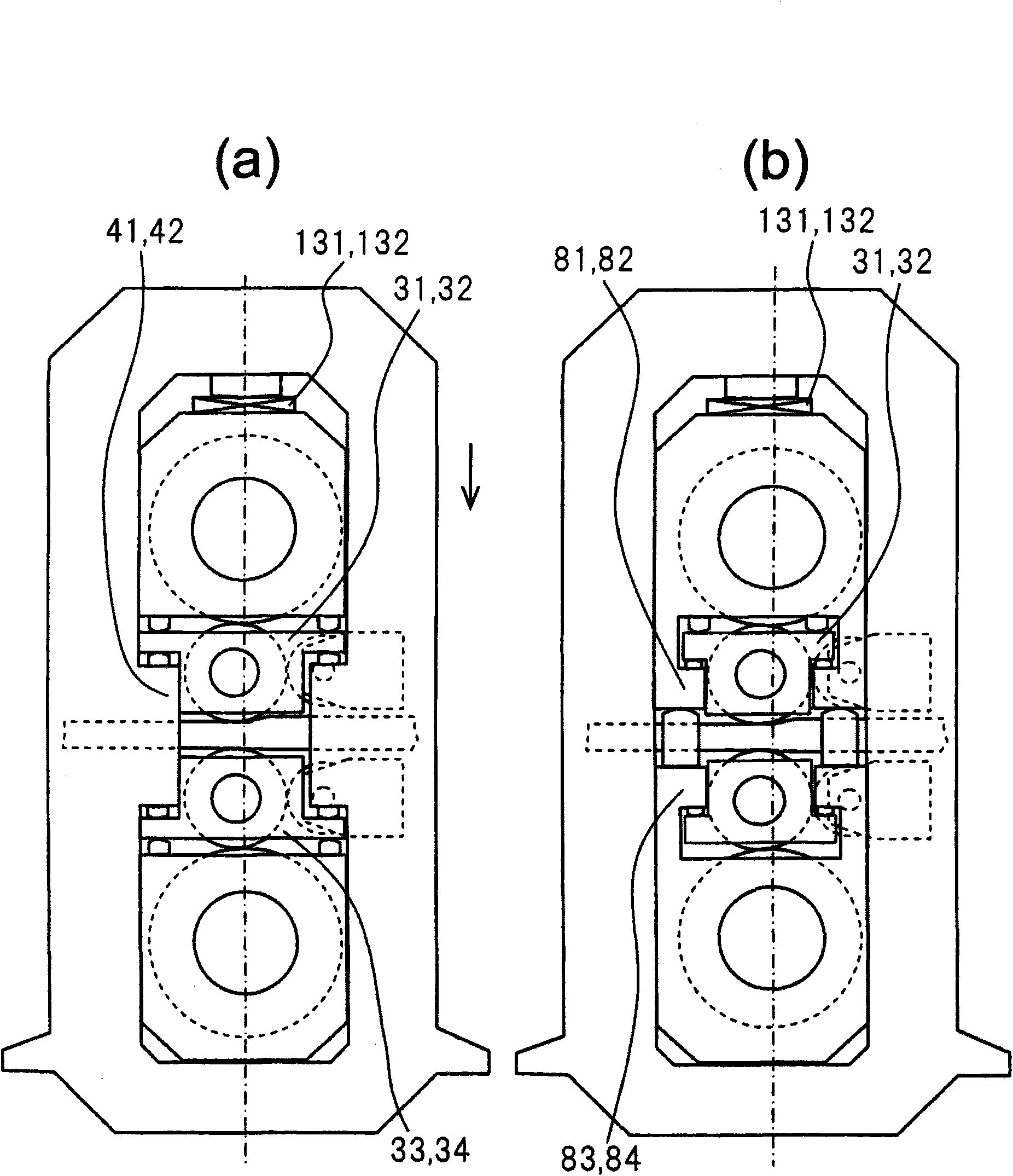
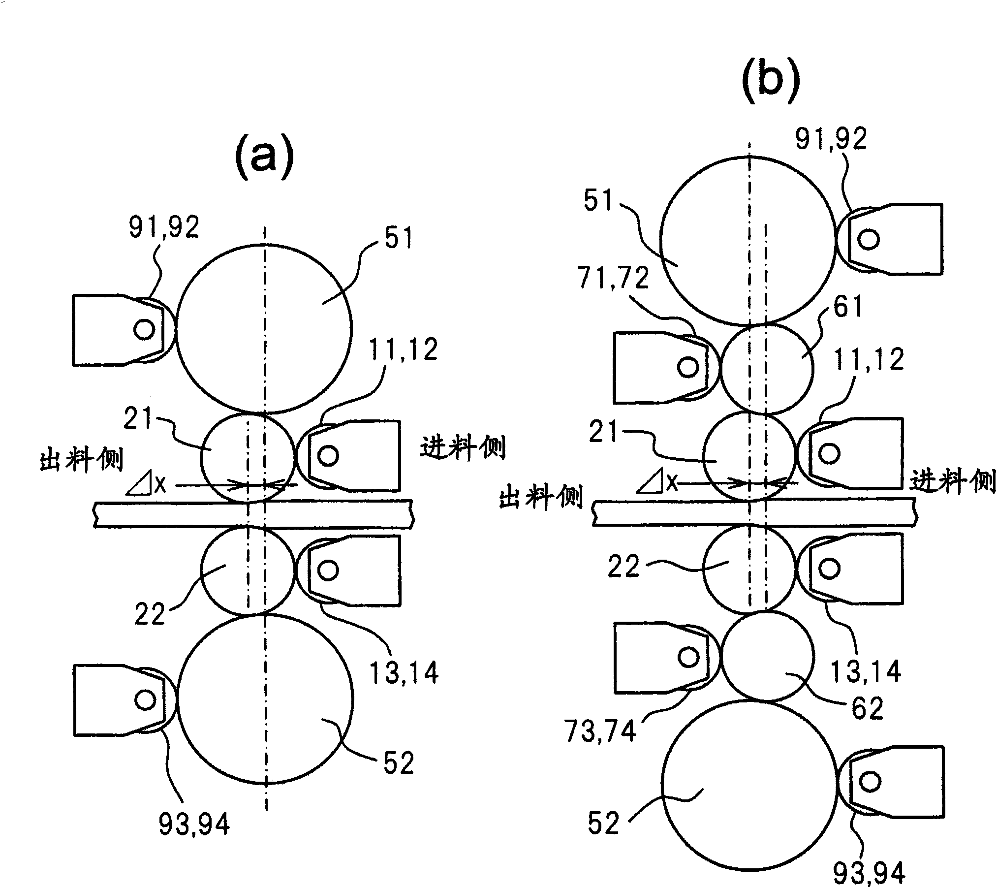
[0068] according to Figure 1 to Figure 10 The best mode for carrying out the present invention will be described in detail.

[0069] exist Figure 1 to Figure 10 , the reference signs are as follows:

[0070] 11, 12, 13, 14 work roll push rollers (11, 12 are upper work roll push rollers, 13, 14 are lower work roll push rollers. The same below, from the rolling line of the rolled material Start referring to the upper side as "upper" and the lower side as "lower")

[0071] 21, 22 work roll

[0072] 31, 32, 33, 34 work roll chocks

[0073] 41, 42 balance weight (rolling mill stand)

[0074] 51, 52 support roller

[0075] 61, 62 middle roller

[0076] 71, 72, 73, 74 middle roller pushing roller

[0077] 81, 82, 83, 84 Work roll chock support members connected to backup roll chocks

[0078] 91, 92, 93, 94 support roller push roller

[0079] 101, 102 work roll horizontal direction load detection device

[0080] 111, 112 push roller load detection device

[0081] 121, 12...


PUM


Abstract

Disclosed is a plate rolling mill wherein a kiss roll-tightening state such as zero point adjusting work before rolling, and deviations in offset of work rolls in the right / left or up / down directions of a rolling mill during rolling are eliminated, and such problems as warpage of a plate and meandering or camber caused by a thrust force produced between a work roll and a reinforcing roll are eliminated. The plate rolling mill comprises a pair of upper and lower work rolls being driven by an electric motor, a pair of upper and lower reinforcing rolls for supporting rolling reactions being loaded on to the work rolls by touching the work rolls, and a device for loading an external force substantially in the horizontal direction on to the upper and lower work rolls, respectively, characterized in that the external force in the horizontal direction being loaded on to the work rolls is in the same direction as the horizontal components of rolling reactions being loaded on to the work rolls by offset in the rolling direction, and the external force in the horizontal direction loaded on to the work rolls is supported by the project block of a rolling mill housing or a supporting member of a work roll chock. A plate rolling method using the plate rolling mill is also provided.

Description

technical field [0001] The present invention relates to a flat rolling mill having work rolls driven by a motor, backup rolls supporting a rolling reaction force loaded on the working rolls, and a flat rolling method using the flat rolling mill. Background technique [0002] In a flat rolling mill having work rolls driven by a motor and back-up rolls supporting the rolling reaction force loaded on the work rolls, the axial center positions of the work rolls and the back-up rolls are shifted to provide a rolling direction offset at a certain interval The amount (off set) makes it generate the horizontal direction (unless otherwise specified, the so-called horizontal direction refers to the rolling direction) component force of the rolling reaction force, pushing the work roll chocks to the inside of the rolling mill stand window, etc., by This method of rolling a steel plate in a stable shape is adopted, and various proposals have been made conventionally. [0003] For examp...

Claims


Application Information

Patent Timeline
Patent Type & Authority Applications(China)
IPC IPC(8): B21B29/00B21B13/14B21B37/00
CPCB21B2013/025B21B38/105B21B2013/026B21B13/145B21B2031/206B21B2013/028
Inventor 小川茂石井笃河西大辅
Owner NIPPON STEEL CORP
Learn More