Footwear sole component with a single sealed chamber

a sole component and shoe sole technology, applied in heels, non-surgical orthopedic devices, medical science, etc., can solve the problems of limited deflection by foam density, rapid compression set, and increased stiffness of foam elastomers, and achieve high deflection and high energy capacity of pneumatic units. , the effect of high deflection

Inactive Publication Date: 2005-12-22
NIKE INC
View PDF73 Cites 11 Cited by
  • Summary
  • Abstract
  • Description
  • Claims
  • Application Information

AI Technical Summary

Benefits of technology

[0024] The present invention pertains to a sole component for footwear incorporating a sealed, fluid containing chamber and resilient material to harness the benefits of both a pneumatic system and a mechanical system, i.e., provide a large deflection at high impact, controlled stiffness response, a smooth transition to maximum deflection and stability. The sole component of the present invention is specifically designed to optimally combine pneumatic and mechanical structures and properties. The sealed, fluid containing chamber can be made by sealing an appropriately shaped void in the resilient material, or forming a bladder of resilient barrier material.
[0025] Recognizing that resilient material, such as a foamed elastomer, and air systems each posses advantageous properties, the present invention focuses the design of cushioning systems combining the desirable properties of both types, while reducing the effect of their undesirable properties.

Problems solved by technology

That is, as the compression load increases, foamed elastomers become or feel increasingly stiff.
The undesirable properties of foamed elastomers include limitations on deflection by foam density, quick compression set, and limited design options.
Some difficulties of designing gas filled bladder systems include instability and the need to control the geometry of the bladder.
Constraining this tendency can require complex manufacturing methods and added elements to the sole unit.

Method used


Image

  • Footwear sole component with a single sealed chamber
  • Footwear sole component with a single sealed chamber
  • Footwear sole component with a single sealed chamber

Examples


Embodiment Construction

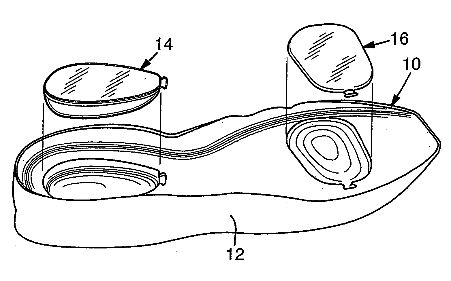
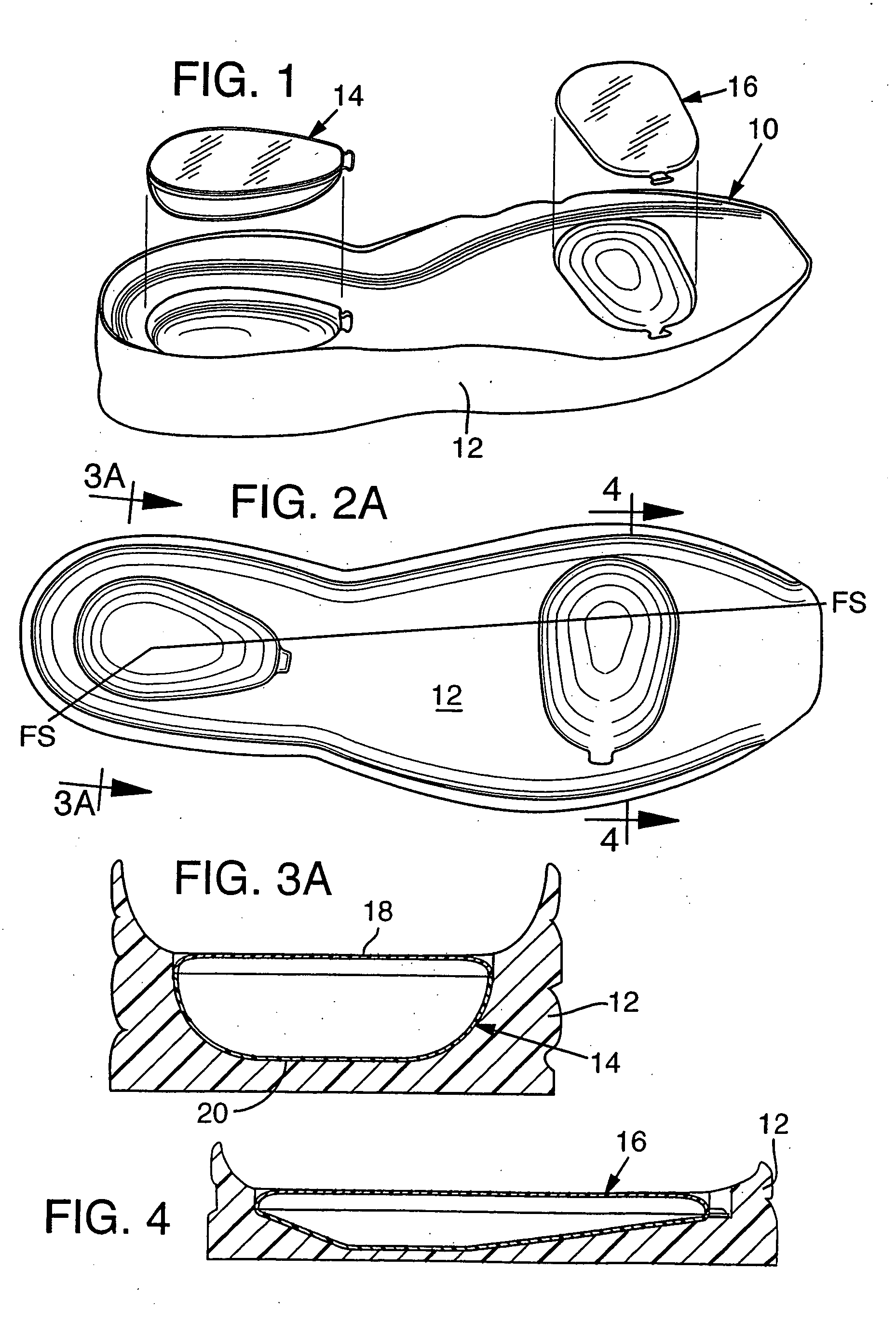
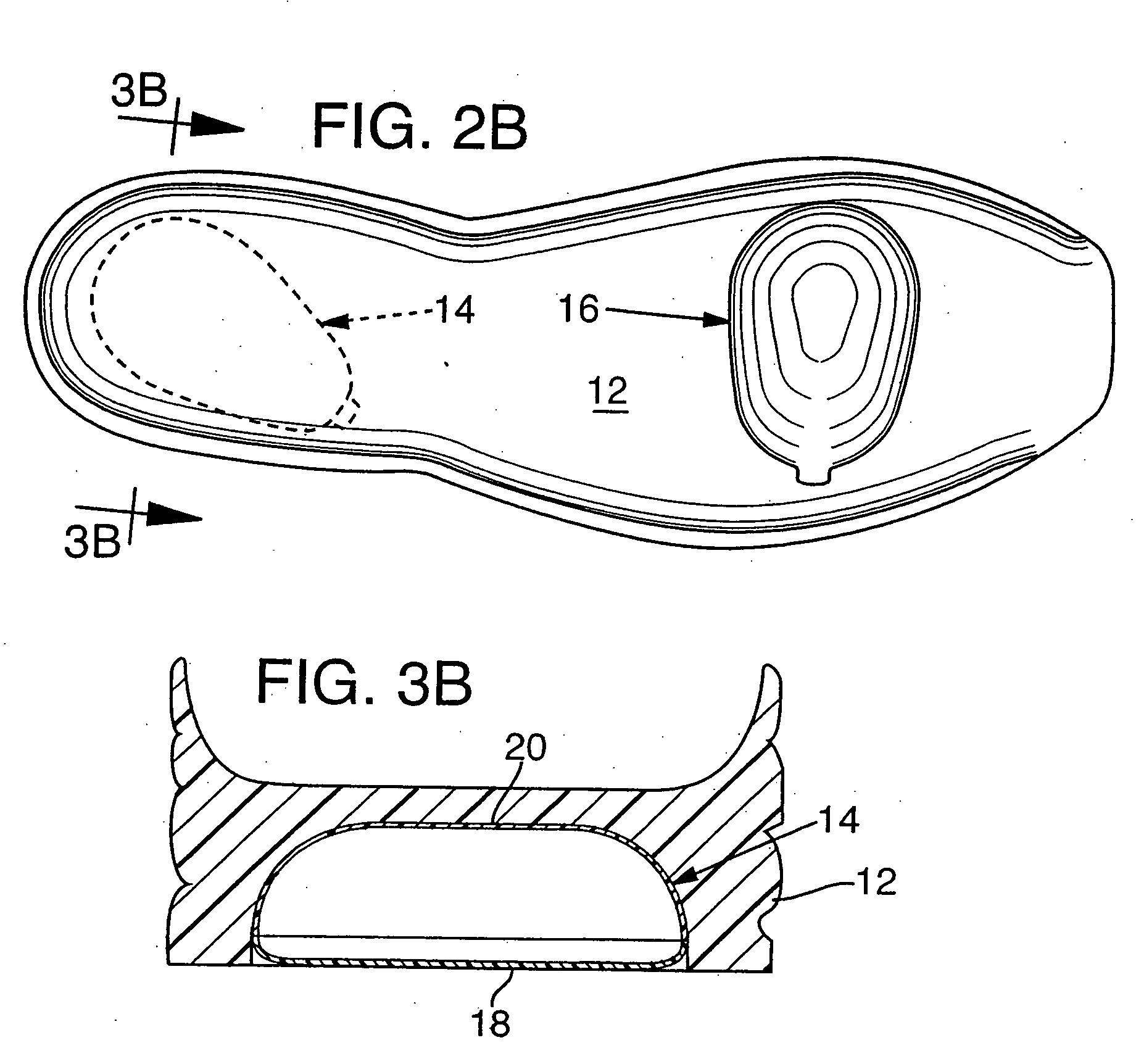
[0060] Sole 10 of the present invention includes a midsole 12 of an elastomer material, preferably a resilient foam material and one or more air bladders 14, 16 disposed in the midsole. FIGS. 1-4 illustrate a cushioning system with a bladder 14 disposed in the heel region and a bladder 16 disposed in the metatarsal head region, the areas of highest load during footstrike. The bladders are used to form sealed chambers of a specific shape. In an alternate embodiment a sealed chamber can be formed from a void in an elastomeric chamber that is sealed with a separate cover material. The shape of the chambers and their arrangement in the elastomeric material, particularly in the heel region, produces the desired cushioning characteristics of large deflection for shock absorption at initial footstrike, then progressively increasing stiffness through the footstrike.

[0061] The preferred shape of the bladder is a contoured taper shaped outline, preferably pear-shaped, as best seen in FIGS. 5...


PUM


Abstract

A sole component for footwear combining the desirable response characteristics of a fluid filled chamber and an elastomeric material. The chamber can be formed as a single bladder chamber in contact with an elastomeric midsole, or a single chamber formed by a sealing a void in elastomeric material. The interface between the chamber and elastomeric material is sloped and gradual so that the shape of the chamber and its placement in a midsole determine the combination of response characteristics in the sole component. The chamber has a relatively simple shape with one axis of symmetry with a rounded portion and a narrow portion.

Description

CROSS-REFERENCE TO RELATED APPLICATIONS [0001] This U.S. Patent application is a continuation application of and claims priority to U.S. patent application Ser. No. 10 / 845,302, which was filed in the U.S. Patent and Trademark Office on May 14, 2004 and entitled Footwear Sole Component With A Single Sealed Chamber, such prior U.S. Patent Application being entirely incorporated herein by reference. U.S. patent application Ser. No. 10 / 845,302 is, in turn, a divisional application of U.S. patent application Ser. No. 10 / 143,745, which issued as U.S. Pat. No. 6,796,056 on Sep. 28, 2004.BACKGROUND OF THE INVENTION [0002] 1. Field of the Invention [0003] The present invention relates to an improved cushioning system for athletic footwear which provides a large deflection for cushioning the initial impact of footstrike, a controlled stiffness response, a smooth transition to bottom-out and stability, and more specifically to a system which allows for customization of these response character...

Claims


Application Information

Patent Timeline
Patent Type & Authority Applications(United States)
IPC IPC(8): A43B13/18A43B13/20
CPCA43B7/144A43B13/20A43B13/189A43B13/187A43B13/18
Inventor SWIGART, JOHN F.
Owner NIKE INC
Why Eureka
Try Eureka