
Electric power steering device

a technology of electric power steering and absorbing member, which is applied in the direction of electrical steering, mechanical equipment, transportation and packaging, etc., can solve the problems of insufficient gear strength of the rack shaft and the pinion, and achieve the effects of reducing toughness, reducing the amount of deflection, and increasing the rigidity of the absorbing member

Inactive Publication Date: 2005-08-04
NSK LTD
View PDF3 Cites 13 Cited by
  • Summary
  • Abstract
  • Description
  • Claims
  • Application Information

AI Technical Summary

Benefits of technology

[0006] The present invention has been made in view of such problems of the known techniques, and it is an object of the present invention to provide an electrically driven power steering apparatus with a simple structure, which can prevent overloading of an electrical motor and a power transmission system.
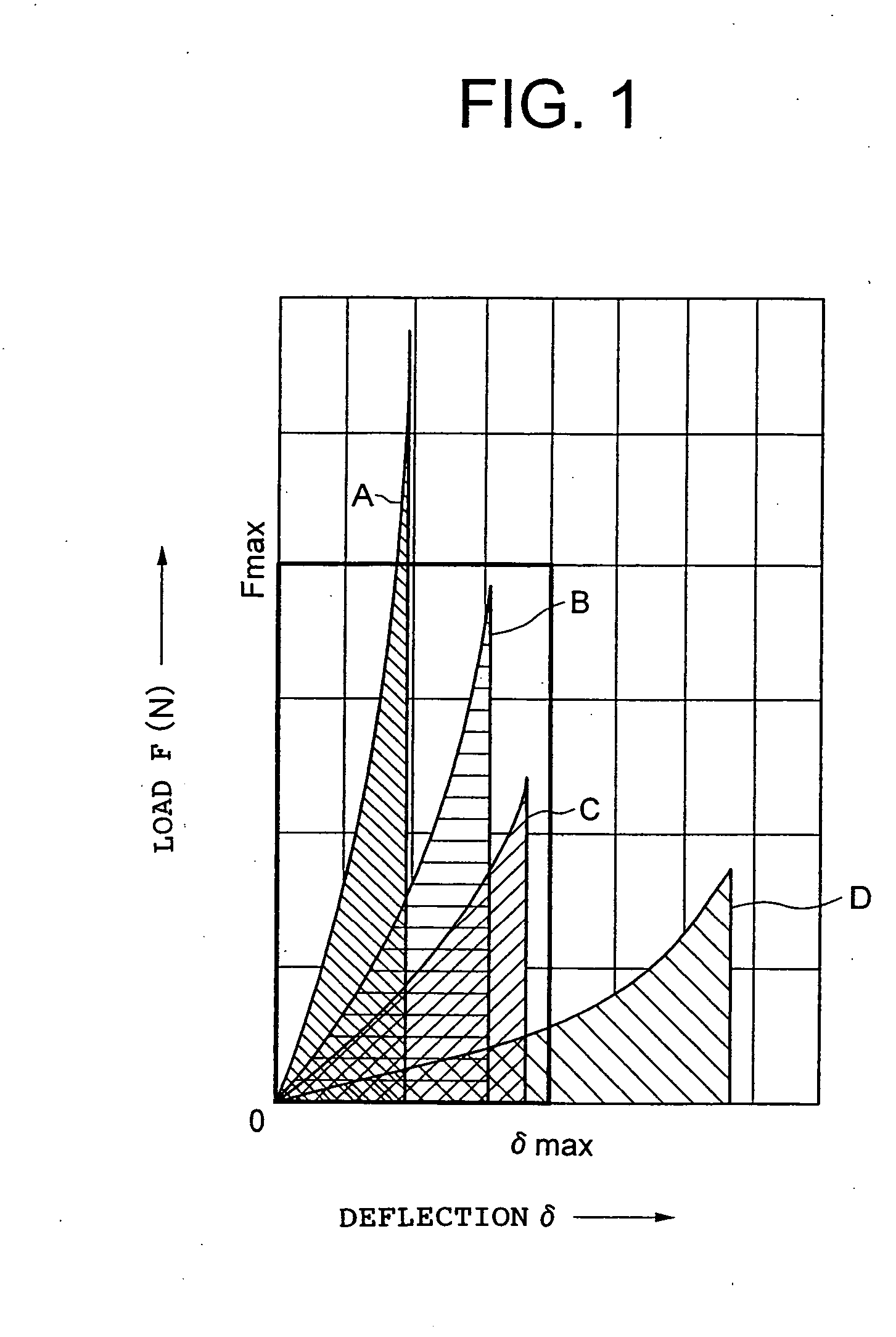
[0011] Accordingly, in the present invention, the amount of the maximum deflection of the absorbing member is suppressed by contacting the face of the absorbing member at the end of the reciprocal movement of the moving shaft. Furthermore, while the amount of the deflection is kept small at least partially using a material having a Young's modulus 100 to 900 Mpa for the absorbing member, the impact at the end (stroke end) of the reciprocal movement of the moving material is effectively relieved.
[0019] An electrically driven power steering apparatus according to the second invention includes: a housing; a motor attached to the housing; a moving shaft to which an assistive steering force is inputted from the motor, and which is reciprocally movable within a range restricted by the housing in order to steer wheels; an input shaft connected to a steering wheel; power transmission means which connects the input shaft with the moving shaft in a power transmissible manner; an absorbing member which is attached to the moving shaft, and is brought into contact with the housing in face-to-face relation at an end of the reciprocal movement of the moving shaft; wherein the absorbing member includes a metal member and an elastic member formed by rubber or resin material, the metal member has a hole extending in the axial direction, and the elastic member attached to both ends of the metal member in the axial direction are connected through the hole. Therefore even if the adhesive strength between the metal member and the elastic member is not increased, the separation between the metal member and the elastic member is prevented, which results in excellent durability.
[0020] An electrically driven power steering apparatus according to the third invention includes: a housing; a motor attached to the housing; a moving shaft to which an assistive steering force is inputted from the motor, and which is reciprocally movable within a range restricted by the housing in order to steer wheels; an input shaft connected to a steering wheel; power transmission means which connects the input shaft with the moving shaft in a power transmissible manner; an absorbing member which is attached to the moving shaft, and is brought into contact with the housing in face-to-face relation at an end of the reciprocal movement of the moving shaft; wherein the absorbing member includes a metal member and an elastic member formed by rubber or resin material, and the elastic member is disposed at least at one of both end faces of the metal member in the axial direction, and between the metal member and the moving member. Therefore, the absorbing member can be attached without backlash by the elastic member between the metal member and the moving member appropriately deforming without improving the dimensional accuracy of the attachment part of the moving shaft. Also, it is possible to prevent the occurrence of a problem such as getting scratched with each other at the time of attachment, and the like.

Problems solved by technology

However, in an electrically driven power steering apparatus, the inertia becomes about double, and thus, for example, the gear strength of the rack shaft and the pinion might be insufficient.

Method used


Image

  • Electric power steering device
  • Electric power steering device
  • Electric power steering device

Examples


Embodiment Construction

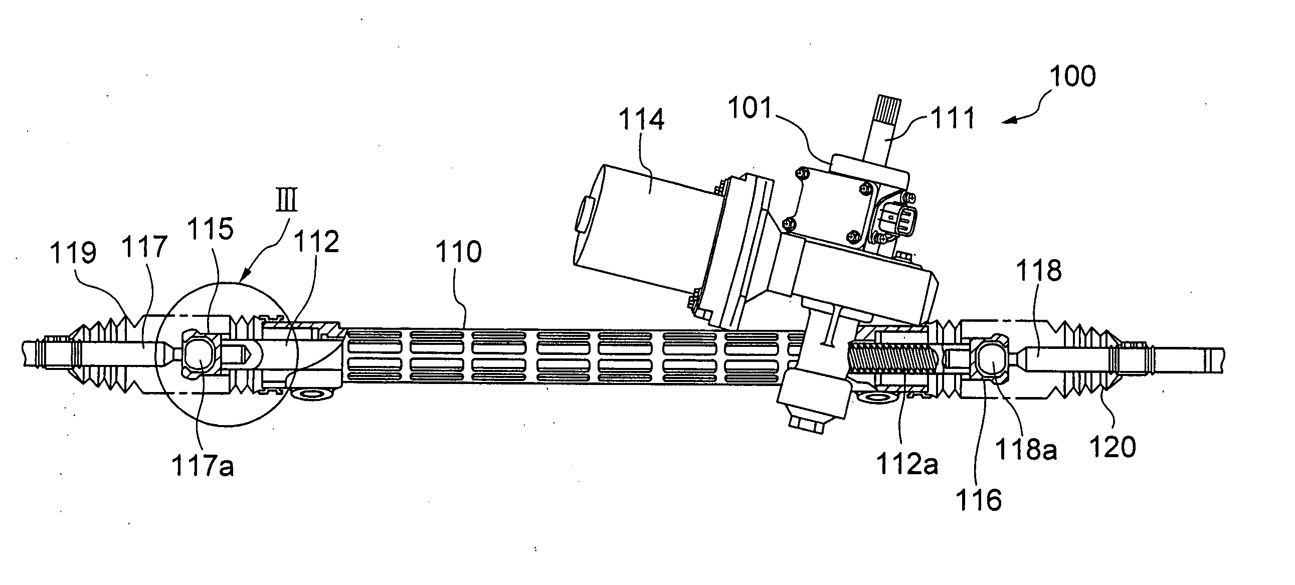
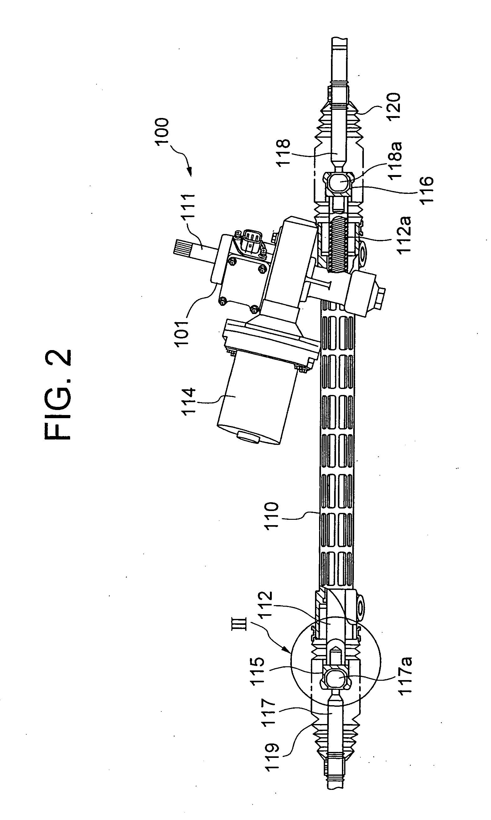
[0035] In the following, a detailed description will be given below of embodiments of the present invention with reference to the drawings. FIG. 2 is a front view, illustrating a partially sectional view in the axial direction, of an electrically driven power steering apparatus 100 according to an embodiment of the present invention.

[0036] In FIG. 2, a housing is constituted by a housing main body 110 and a rack housing 110 extending therefrom in the electrically driven power steering apparatus 100. The housing main body 101 and the rack housing 110 are fixed to an unillustrated car body to integrally constitute the housing through an unillustrated bracket.

[0037] Inside the housing main body 101, an input shaft 111, which is connected to a steering shaft and a steering wheel (not shown) at one end, is extending obliquely from above in FIG. 2. On the other hand, a rack shaft 112, which is a moving shaft, is extending in the housing main body 101 and the rack housing 110. An unillus...


PUM


Abstract

To provide an electrically driven power steering apparatus with a simple structure, which can prevent overloading of an electrical motor and a power transmission system, an absorbing member (121) is attached to a rack shaft (112), and is brought into contact with a rack housing face at a stroke end of the rack shaft (112). The absorbing member (121) at least partially has a material having a Young's modulus of 100 to 900 Mpa, and thus it is possible to effectively relieve an impact at the stroke end.

Description

TECHNICAL FIELD [0001] The present invention relates to an electrically driven power steering apparatus, and more particularly, to an electrically driven power steering apparatus which can suppress the occurrence of noises. BACKGROUND ART [0002] One known type of electrically driven power steering apparatus of a vehicle is that rotational output of an electric motor, which gives an assistive steering torque, is reduced speed by a gear unit, then is transmitted to a moving shaft (rack shaft, etc.) of a steering mechanism, and assists the manual power of a steering wheel so that the moving shaft is moved reciprocally in a predetermined range in order to steer the wheels. Here, a moving member impinges on the rack housing at the stroke end (end) of the moving member, and thereby an impact might occur in the transmission route of the steering apparatus. Such an impact might cause damage on the electric motor and the power transmission mechanism. [0003] In order to relieve or eliminate s...

Claims


Application Information

Patent Timeline
Patent Type & Authority Applications(United States)
IPC IPC(8): B62D3/12B62D5/04B62D7/16
CPCB62D3/12F16C11/0652B62D7/163B62D5/0403F16C2326/24B62D5/04
Inventor ABE, MANABUCHIKARAISHI, KAZUOTANAKA, ATSUSHI
Owner NSK LTD
Learn More