

Hydraulic dynamic bearing and spindle motor
a dynamic bearing and spindle motor technology, applied in the direction of sliding contact bearings, mechanical equipment, mechanical energy handling, etc., can solve the problems of high countermeasure cost, inapplicability, increased etc., and achieve the effect of large deflection of an nrro and efficient generation of high thrust dynamic pressur
- Summary
- Abstract
- Description
- Claims
- Application Information
AI Technical Summary
Benefits of technology
Problems solved by technology
Method used
Image

Examples
Embodiment Construction
[0001] 1. Technical Field to which the Invention Belongs
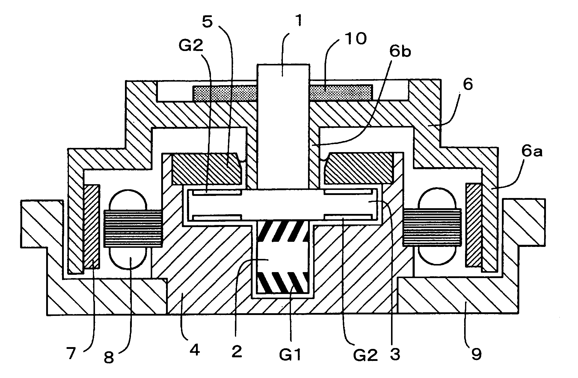
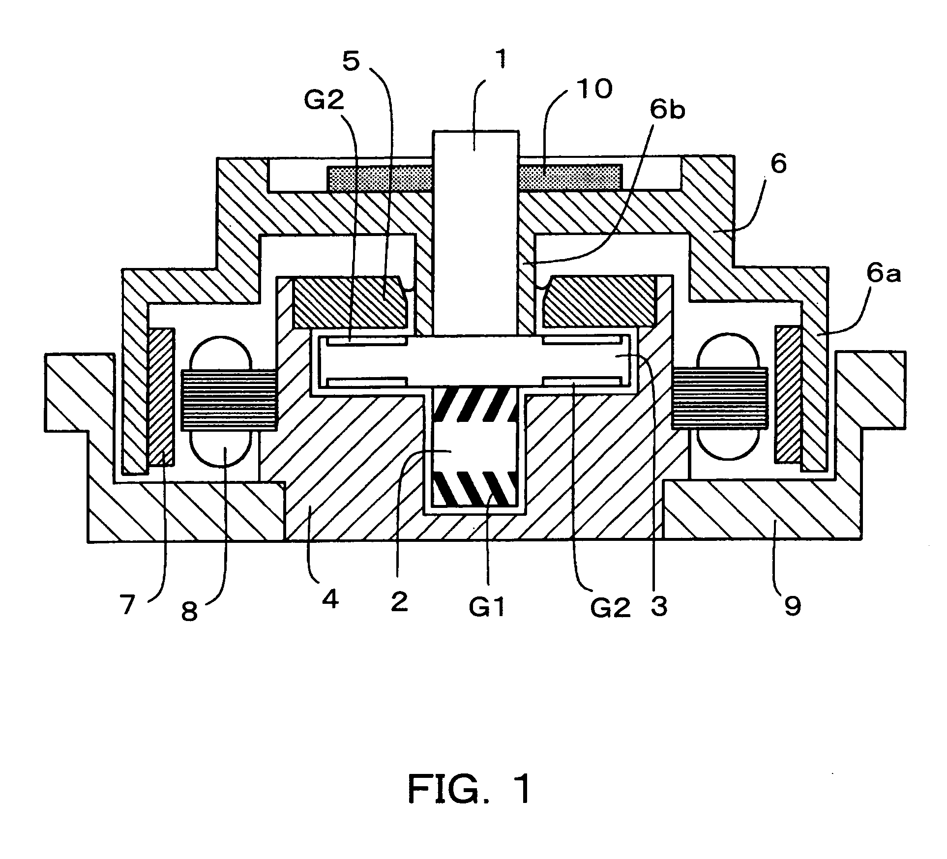
[0002] The present invention relates to a hydraulic dynamic bearing comprising a flanged shaft having a thrust ring portion and a cylinder portion, a single bag-like stepped sleeve in which there are formed in order a small diameter cylinder portion, a large diameter cylinder portion and a cylindrical open end portion, a presser ring pressure-inserted and fixed to the cylindrical open end portion of the sleeve, and a lubricating oil sealed in a fine gap including a thrust gap formed between these bearing constituting members, and to a spindle motor having this hydraulic dynamic bearing. In particular, it relates to a structure of a thrust dynamic pressure generating groove of the hydraulic dynamic bearing.
[0003] 2. Prior Art
[0004] In Japanese Patent Laid-Open No. 32828 / 2001 Gazette, there are disclosed a hydraulic dynamic bearing comprising a flanged shaft having a thrust ring portion and a cylinder portion, a single bag-lik...
PUM
 Abstract
Description
Claims
Application Information