
Methods and apparatuses for detecting pattern errors

A pattern and error technology, applied in the field of detecting pattern errors and devices, can solve the problem of not tending to periodicity, and achieve high-precision effects

Inactive Publication Date: 2010-12-15
MICRONIC LASER SYST AB
View PDF15 Cites 25 Cited by
  • Summary
  • Abstract
  • Description
  • Claims
  • Application Information

AI Technical Summary

Problems solved by technology

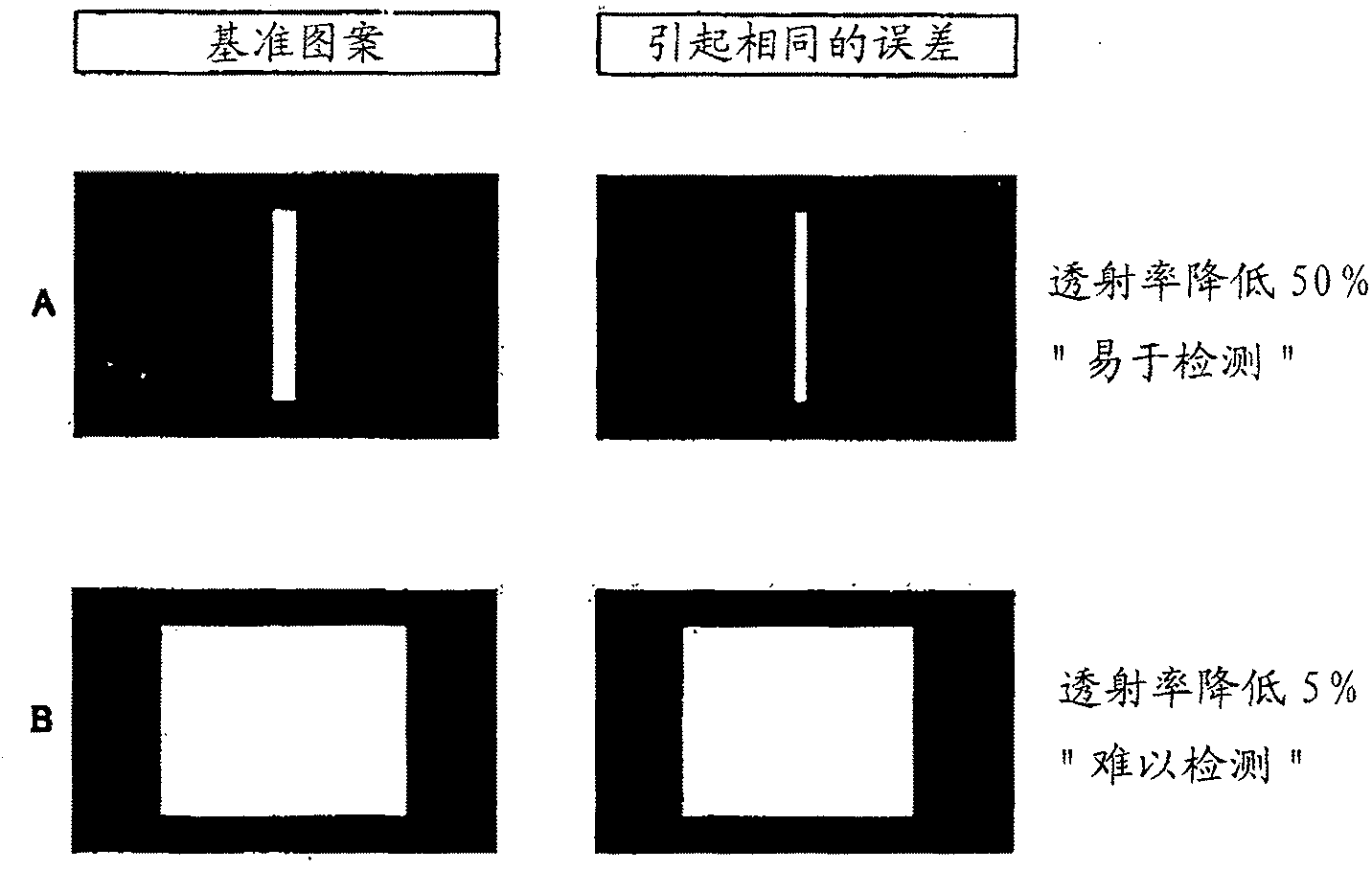
The true defect also modulates the signal, but is not inherently periodic

Method used


Image

  • Methods and apparatuses for detecting pattern errors
  • Methods and apparatuses for detecting pattern errors
  • Methods and apparatuses for detecting pattern errors

Examples


Embodiment Construction

[0080] Various example embodiments of the invention will be described more fully hereinafter with reference to the accompanying drawings, in which some example embodiments of the invention are shown. In the drawings, the thicknesses of layers and regions are exaggerated for clarity.

[0081] Detailed illustrations of embodiments of the invention are disclosed herein. However, specific structural and functional details disclosed herein are merely representative for purposes of describing example embodiments of the present invention. This invention may, however, be embodied in many alternative forms and should not be construed as limited to only the embodiments set forth herein.

[0082] Therefore, while exemplary embodiments of the present invention are capable of various modifications and different forms, the embodiments thereof are shown in the drawings by way of example and will be described in detail herein. It should be understood, however, that there is no intent to lim...


PUM


Abstract

Methods and apparatuses for quality control and detecting errors related to the manufacturing and production of more accurate patterns and resultant devices are provided. The patterns or devices may include patterns used in display applications such as TFT-LCD, OLED, SED, PDP, FED, LTPS-LCD and similar display technologies using at least partially cyclical patterns.

Description

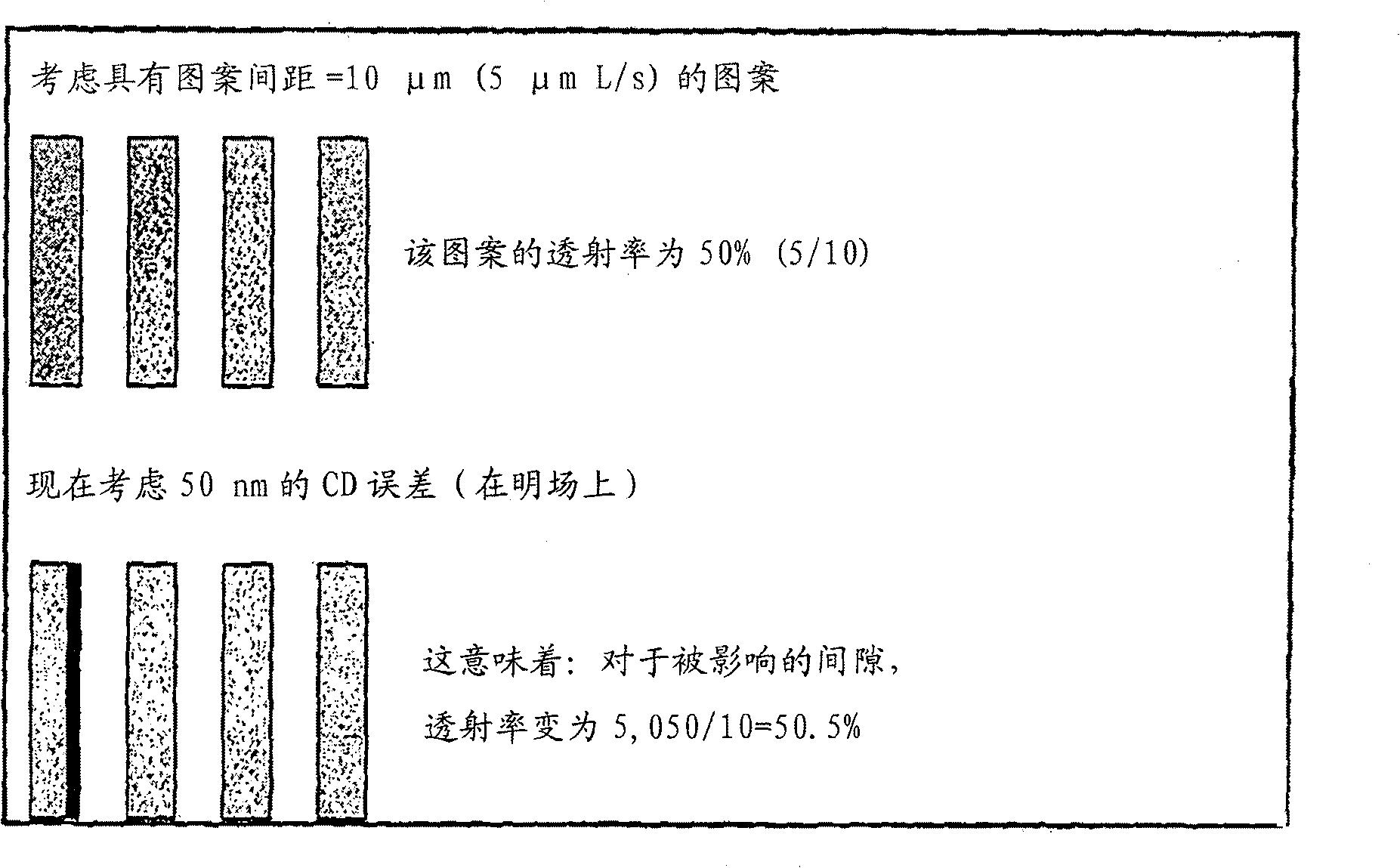
[0001] priority statement [0002] This nonprovisional patent application claims priority under 35 U.S.C. §119(e) to Provisional U.S. Patent Application No. 60 / 987,186 filed in the U.S. Patent and Trademark Office on November 12, 2007, and adopted in its entirety Incorporated here by reference. Background technique [0003] Traditionally, die-to-die inspection for recurring patterns involves comparing a reference image with a recorded image of a portion (eg, a pixel or other repeating pattern unit) of the pattern to be inspected. An example of this method is described in US Patent No. 5,640,200. In this conventional approach, a "golden template" is created based on a number of test images, and this "golden template" is later compared with the test images. [0004] A reference image can be created in a variety of ways, such as averaging many images from different parts of the entire pattern, computing a reference image from data, and so on. But, for example, the accuracy of ...

Claims


Application Information

Patent Timeline
IPC IPC(8): G01N21/956G06T7/00G09G3/00
CPCG01N21/956G06T7/0004G01B11/30G01N21/9501
Inventor 弗雷德里克·肖斯特罗姆彼得·埃克伯格
Owner MICRONIC LASER SYST AB
Learn More