Cutting machine for metal tube

A pipe cutting machine and metal pipe technology, applied in the direction of metal sawing equipment, metal processing equipment, sawing machine equipment, etc., can solve the problems of metal pipe beveling and deformation, metal pipe synchronous horizontal movement, etc., to prevent beveling and deformation Effect

Active Publication Date: 2010-12-22
BAOLAI STAINLESS STEEL TECH (KUNSHAN) CO LTD
View PDF5 Cites 10 Cited by
  • Summary
  • Abstract
  • Description
  • Claims
  • Application Information

AI Technical Summary

Problems solved by technology

[0004] The purpose of the present invention is to overcome the defects and problems that the pipe cutting device in the prior art cannot move horizontally synchronously with the metal pipe, resulting in oblique cutting and deformation of the metal pipe when cutting the metal pipe. The device can move horizontally with the metal pipe synchronously, and complete the cutting of the metal pipe during the movement of the metal pipe, and can effectively prevent the metal pipe from beveling and deformation.

Method used


Image

  • Cutting machine for metal tube
  • Cutting machine for metal tube
  • Cutting machine for metal tube

Examples


Embodiment Construction

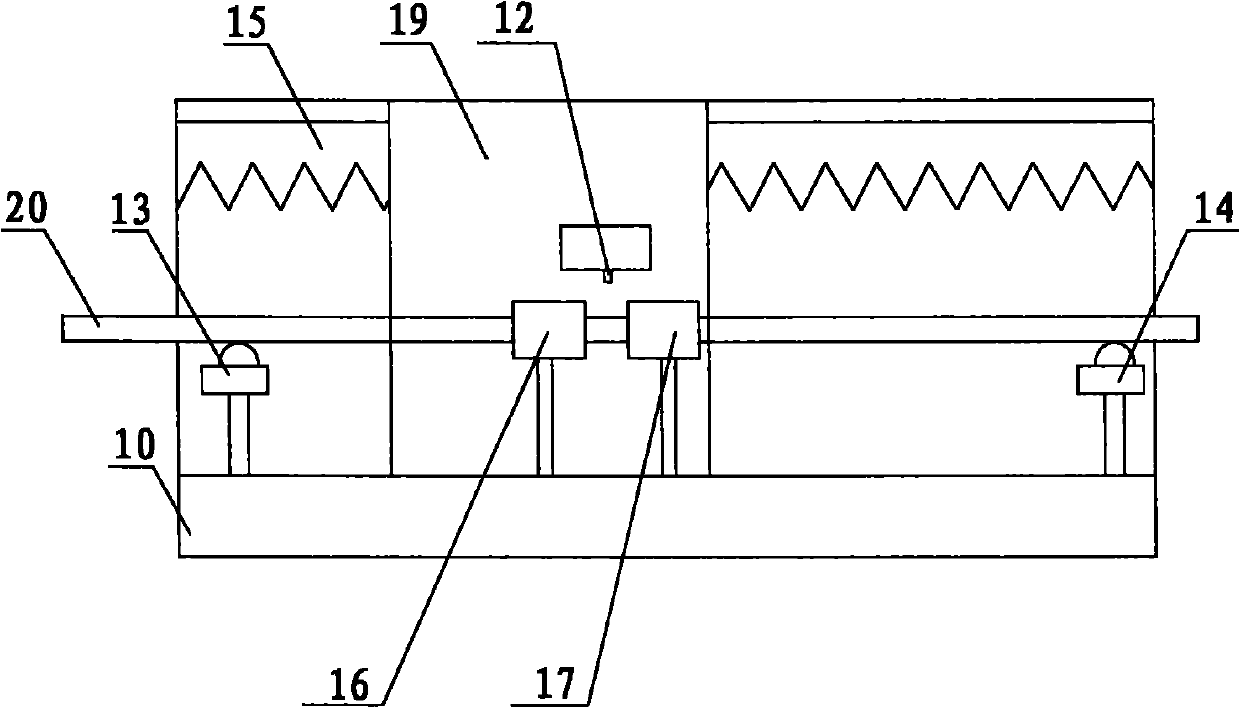
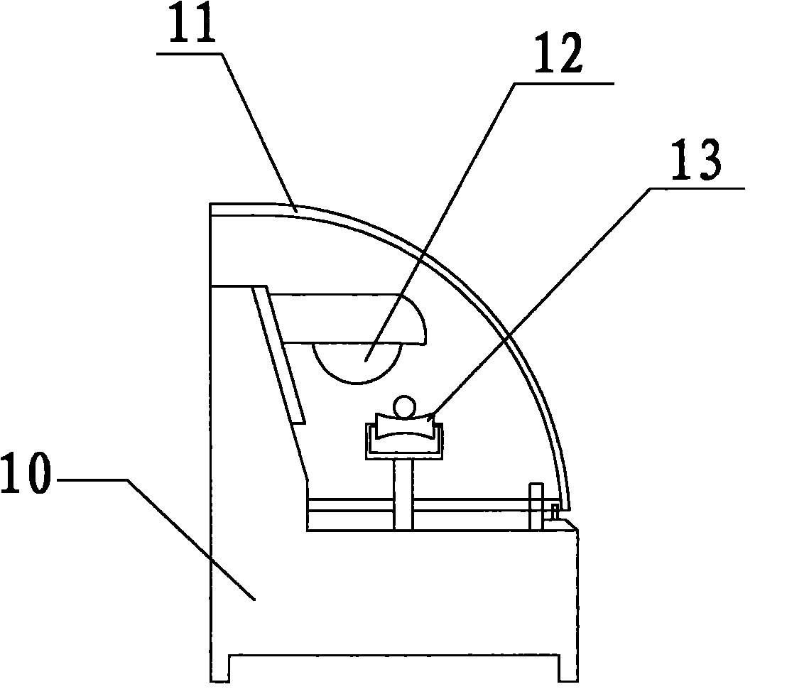
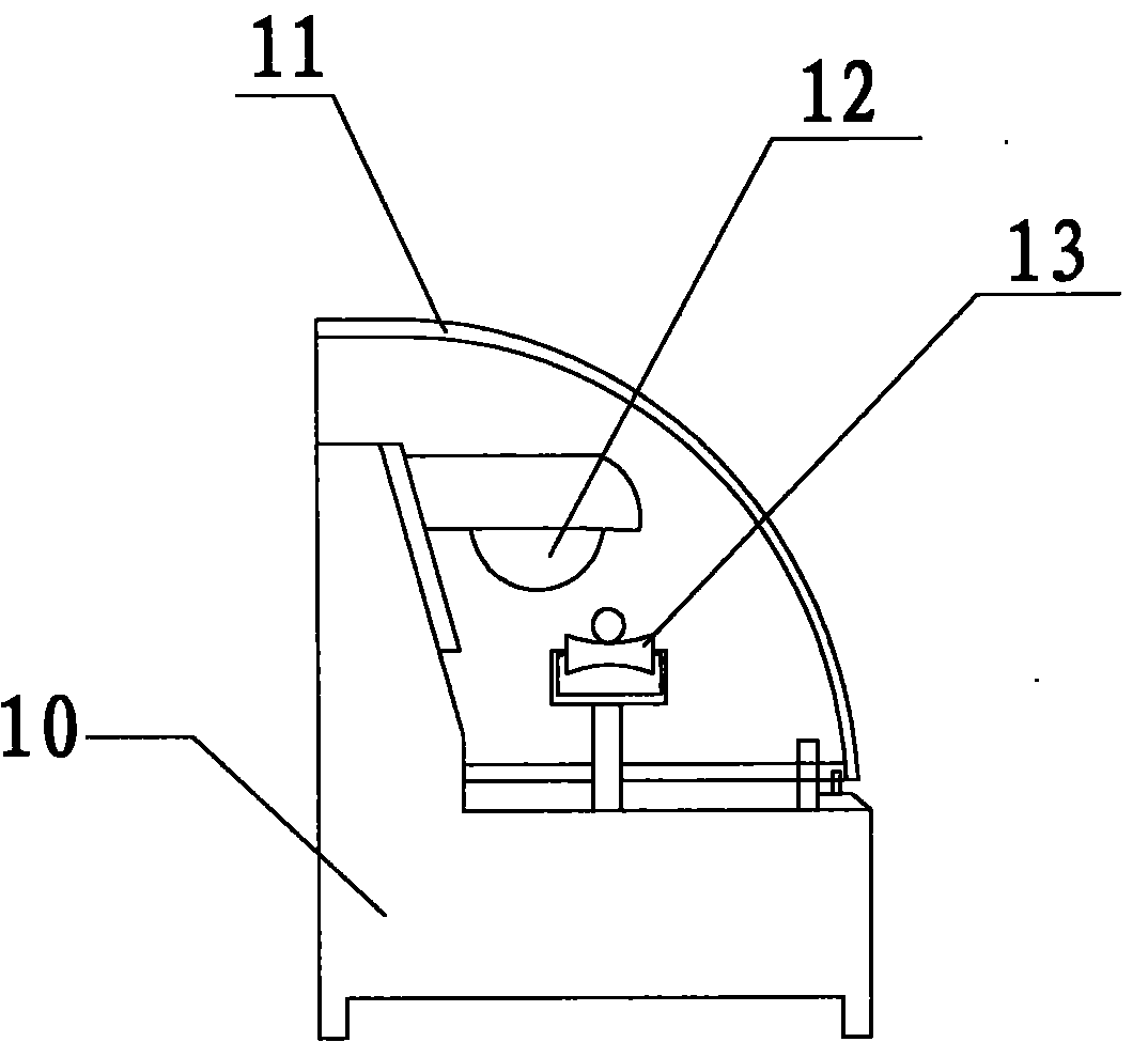
[0012] The present invention will be described in further detail below in conjunction with accompanying drawing and specific embodiment: see figure 1 with figure 2 As shown, a metal pipe cutting machine includes a vertically long machine base 10, and the two ends of the machine base 10 are horizontally provided with a first support frame 13 and a second support frame 14 for supporting the metal pipe 20 to be cut. A box body 11 is also movably arranged on the base 10 , and the box body 11 is located between the first support frame 13 and the second support frame 14 .

[0013] Both sides of the box body 11 are open structures, and the metal pipe 20 can penetrate into the box body 11 from the open opening on one side of the box body 11 and then pass out from the open opening on the other side of the box body 11. The front side of the box body 11 is provided with Glass protective cover 19 is arranged.

[0014] The first clamp 16 and the second clamp 17 are fixedly arranged in t...


PUM


Abstract

The invention discloses a cutting machine for a metal tube, which comprises a lengthwise base, wherein, a first support and a second support for supporting the metal tube are oppositely and horizontally arranged on two ends of the base. The cutting machine is characterized in that a box is movably arranged on the base and positioned between the first support and the second support; the metal tube can penetrate into the box from one side thereof and penetrate out of the box from the other side thereof; the box is internally equipped with a first fixture and a second fixture at an interval for clamping the metal tube; and a cutting device is arranged in a spacing area between the first fixture and the second fixture. When the cutting machine using the structure is used for cutting the metal tube, the cutting device can horizontally move with the metal tube synchronously and complete cutting the metal tube during the movement process of the metal tube so as to effectively prevent the metal tube from being bevelled and deformed.

Description

technical field [0001] The invention relates to a cutting machine, in particular to a metal pipe cutting machine, which is especially suitable for cutting stainless steel metal pipe fittings. Background technique [0002] At present, in general pipe fitting processing operations, in order to meet the needs of pipe fitting design, in addition to the process step of trimming the welding seam of the pipe fitting, it also includes the cutting step according to the length of the pipe fitting design. The cutting step It can be combined with the welding seam repair step and continued. [0003] China Patent Authorization Announcement No. CN2877930Y, the utility model patent dated March 14, 2007 discloses a pipe cutting machine, which is composed of two parts, the control system and the pipe cutting machine. The pipe cutting machine is composed of a transmission The main shaft is fixedly installed on the box by bearings, the movement of the main shaft is driven by the gear driven by...

Claims


Application Information

Patent Timeline
Patent Type & Authority Applications(China)
IPC IPC(8): B23D47/00
Inventor 李水波
Owner BAOLAI STAINLESS STEEL TECH (KUNSHAN) CO LTD
Why Eureka
Try Eureka