Manual nailing gun

A nail gun, manual technology, applied in the field of manual nail gun, can solve the problem of labor and other problems

Inactive Publication Date: 2010-12-22
季纯一
View PDF0 Cites 0 Cited by
  • Summary
  • Abstract
  • Description
  • Claims
  • Application Information

AI Technical Summary

Problems solved by technology

No. 3 application, but it is still laborious to turn the handle with fingers or palms

Method used


Image

  • Manual nailing gun
  • Manual nailing gun

Examples


Embodiment Construction

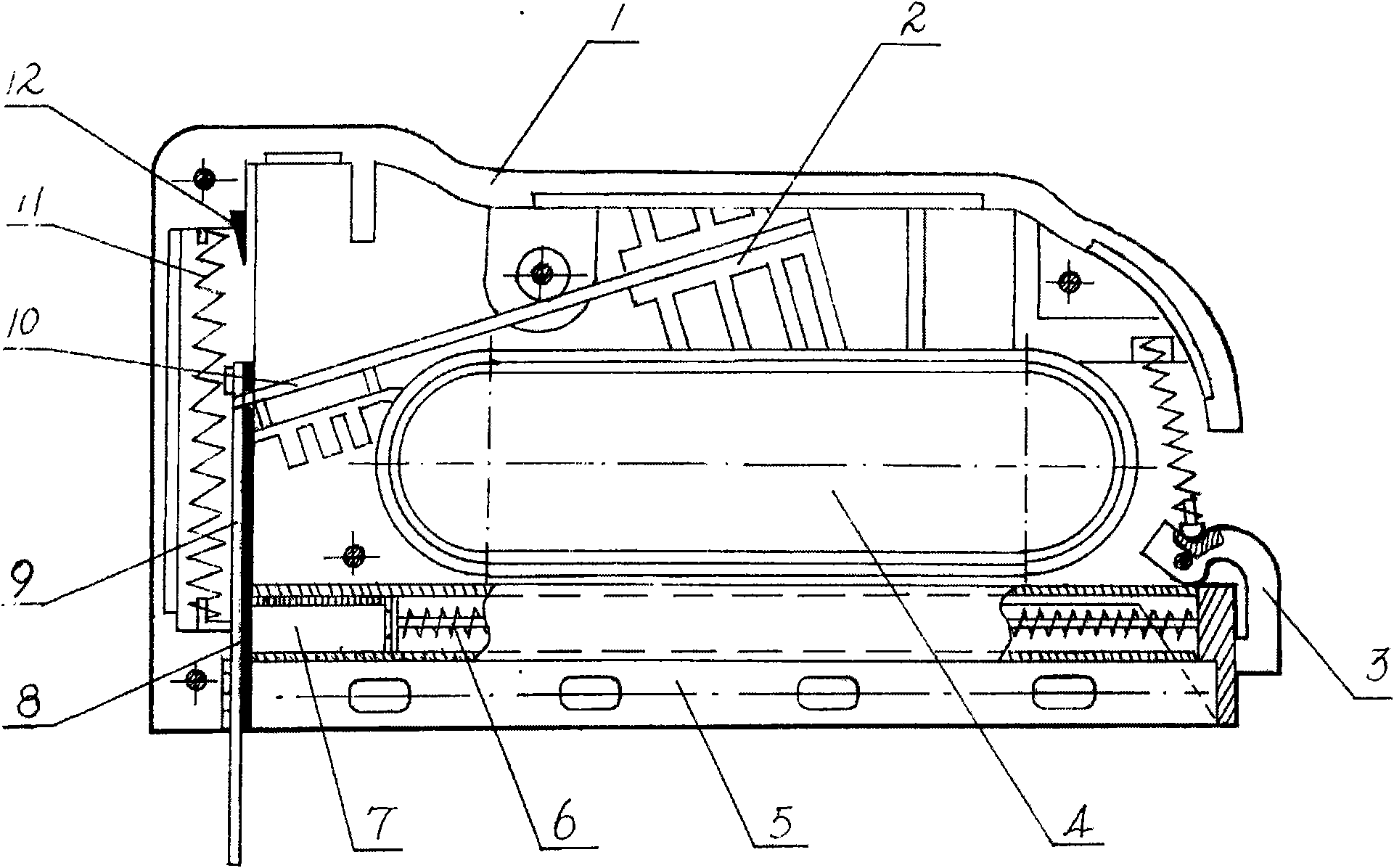
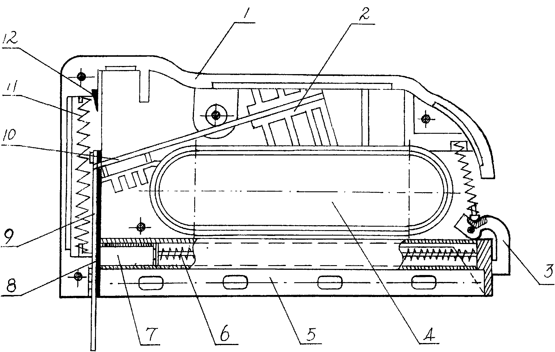
[0007] See attached figure 1 , the present invention comprises casing 1, three sets of spring devices in the casing, rear card 3 and handshake hole 4 are arranged on the casing, one of three sets of spring devices is nail box 7 and push rod spring nail feeding device 6, nail box and nail feeding device The device is mounted on the base 5, the second spring device is the top plate 9 and the spring nailing device, the spring nailing device is close to the impact spring 8 of the nail box 7, the shrapnel 10 and the ejector pin 12 located at the top of the impact spring moving groove, One end of the shrapnel 10 is connected with the impact spring, and the other end is fixed on the shrapnel seat 2. The third spring device is the top piece return spring device. The top piece return spring device includes the top piece and the return spring 11. It is connected with the impact spring with an elastic pin. The operation process of this manual nail gun is that the builder holds the nail g...


PUM


Abstract

The invention relates to a manual nailing gun which comprises a shell and three sets of spring devices in the shell, wherein the first spring device comprises a nail box and a push rod spring nail feed device; the second spring device is a jacking piece and spring nail striking device and comprises a striking spring close to the nail box, an elastic piece and a top pin arranged at the top of a striking spring move slot; and the third spring device comprises a jacking piece and a return spring. The nailing gun is suitable for decoration and civil engineering, does not need a power supply and an air compressor and strikes nails in a pressing mode without causing the fatigues of fingers and the wrists easily; and the top piece is positioned, thus the nailing position is accurate.

Description

【Technical field】 [0001] The invention relates to a manual nail gun, which belongs to the category of hand-held nail tools. 【Background technique】 [0002] In my country's decoration and carpentry construction projects, in addition to the ancient method of nailing with a hammer, generally a pneumatic nail gun driven by an air compressor is used. Although this nail gun reduces people's work, it has the following Disadvantages: Electricity and air compressor are needed, and the air compressor produces noise. Not only does the air compressor need to be placed on a certain site, but the pneumatic nail gun must also be connected to it, which is inconvenient for construction. The air compressor needs to work intermittently to maintain the air pressure. Pneumatic gun work, someone proposes the application of manual nail gun, as the 91219212 of announcement on May 27th, 1992. No. 1 application and 93221968 of announcement on August 3rd, 1994. No. 3 application, but will tilt handle wi...

Claims


Application Information

Patent Timeline
Patent Type & Authority Applications(China)
IPC IPC(8): B25C1/02
Inventor 季纯一
Owner 季纯一
Why Eureka
Try Eureka