Support structure for cooling unit for vehicle
A technology of cooling unit and supporting structure, which is applied to the arrangement of cooling combination of power plant, vehicle components, vehicle safety arrangements, etc., which can solve the problems of cooling unit damage, cooling unit distortion, cooling unit cannot move smoothly, etc., to achieve The effect of high degree of freedom
- Summary
- Abstract
- Description
- Claims
- Application Information
AI Technical Summary
Problems solved by technology
Method used
Image

Examples
no. 1 example
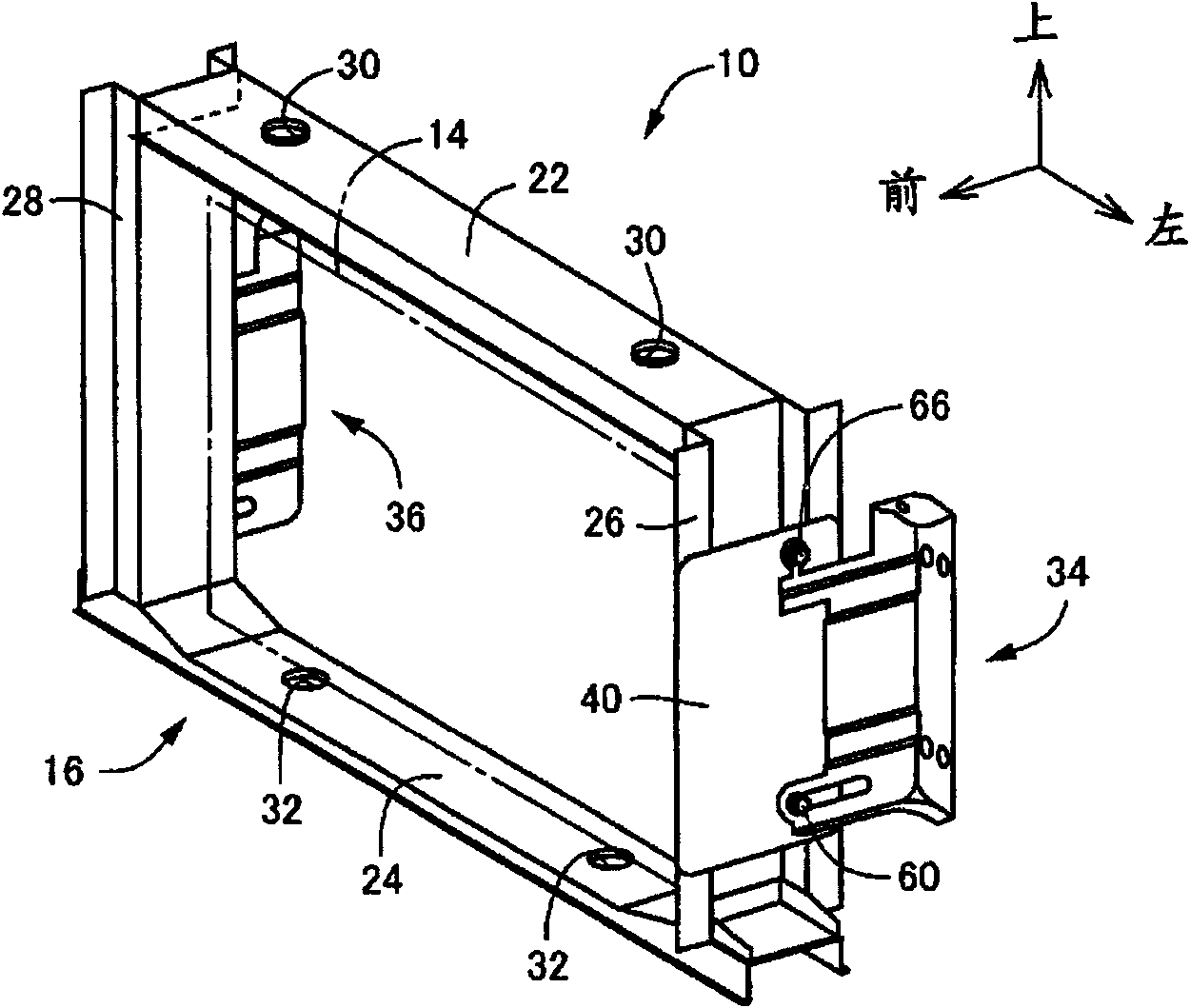
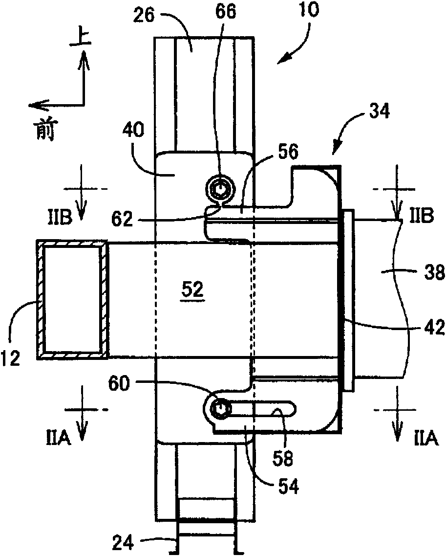
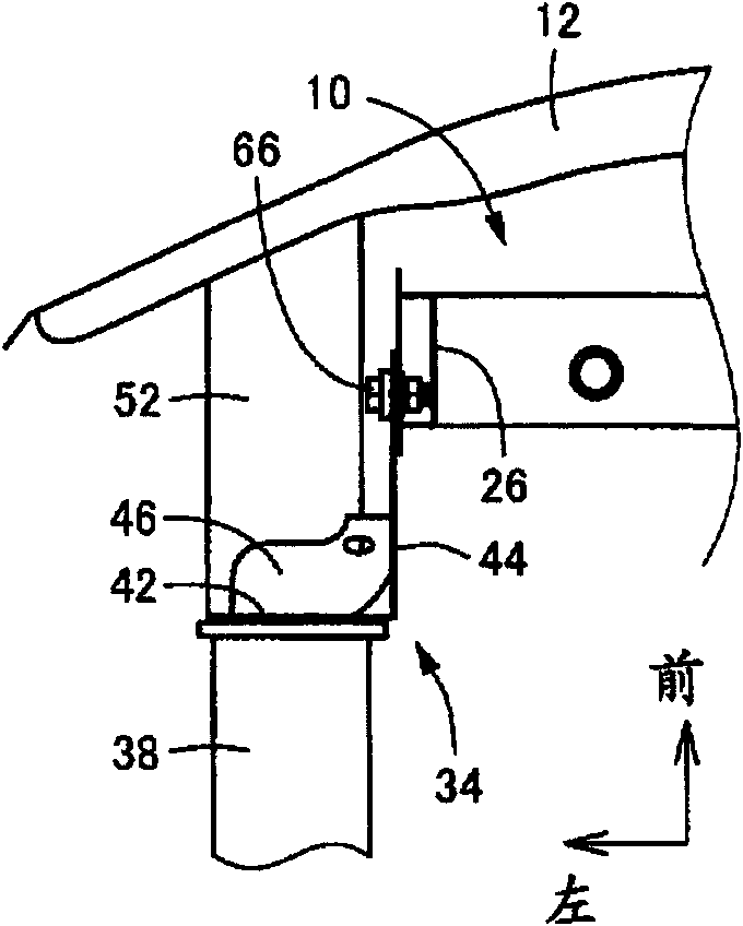
[0039] Hereinafter, a first embodiment of the present invention will be described in detail with reference to the drawings. Figures 1A to 1C is a diagram showing a support structure for a cooling unit for a vehicle according to a first embodiment of the present invention. Figure 1A is a schematic perspective view, Figure 1B is a side view from the left side of the vehicle showing the support structure on the left side of the vehicle, and Figure 1C is a top view showing the support structure on the left side of the vehicle, seen from above the vehicle. The cooling unit 10 in the first embodiment is a radiator that cools a cooling fluid for cooling the engine. The cooling unit 10 includes a rectangular radiator body 14 , and a radiator support 16 in the form of a frame that supports the radiator body 14 . The cooling unit 10 is disposed substantially parallel to the width direction of the vehicle at a position behind the bumper reinforcement 12 disposed on the front side ...
no. 2 example
[0055] Next, a second embodiment of the present invention will be described. In the second embodiment, substantially the same parts as in the first embodiment will be denoted by the same reference numerals, and detailed description thereof will be omitted.
[0056] Figure 6 The diagram is for the Figure 1B A side view of is used to illustrate the support structure utilizing the bracket 70 on the left. Figure 7A and 7B are shown respectively Figure 6 Sectional views of enlarged section VIIA-VIIA and enlarged section VIIB-VIIB in . Figure 8 is a perspective view showing only the bracket 70 . Like the bracket 34 , the bracket 70 is integrally provided with the fixing plate portion 42 , the support plate portion 44 , and the connecting plate portions 46 and 48 . The fixing plate portion 42 is integrally fixed to the front end surface of the front side member 38 , and the support plate portion 44 supports the side radiator support 26 . The support plate portion 44 is in...
no. 3 example
[0065] Figures 11 to 14 A bracket 90 in a third embodiment is shown. When the bracket 90 in the third embodiment is compared with the bracket 70 in the second embodiment, the bracket 90 is different from the bracket 70 in that a substantially horizontal An elongated hole 92 extends linearly, and the first fastening bolt 78 is movable toward the rear side of the vehicle along the elongated hole 92 . Figure 11 is corresponding to Figure 6 side view. Figure 12A and 12B are shown respectively Figure 11 Sectional views of enlarged section XIIA-XIIA and enlarged section XIIB-XIIB in . Figure 13 It is a perspective view showing only the bracket 90 . Figure 14 It is a side view showing a state where the cooling unit 10 has been displaced toward the vehicle rear side.
[0066] The position of the elongated hole 92 is set so that in such as Figure 11 In the normal state shown, the first fastening bolt 78 is screwed onto the reinforcing plate 40 at the front end of the elo...
PUM
 Abstract
Description
Claims
Application Information
 - R&D
- Intellectual Property
- Life Sciences
- Materials
- Tech Scout
- Unparalleled Data Quality
- Higher Quality Content
- 60% Fewer Hallucinations
Browse by: Latest US Patents, China's latest patents, Technical Efficacy Thesaurus, Application Domain, Technology Topic, Popular Technical Reports.
© 2025 PatSnap. All rights reserved.Legal|Privacy policy|Modern Slavery Act Transparency Statement|Sitemap|About US| Contact US: help@patsnap.com