Vacuum device

A vacuum equipment and low-vacuum technology, applied in the direction of mechanical equipment, liquid variable displacement machinery, machines/engines, etc., can solve the problems of multiple energy sources, increase the maintenance cost of vacuum equipment 100, and achieve the effect of saving energy

Inactive Publication Date: 2010-12-22
AU OPTRONICS CORP
View PDF3 Cites 29 Cited by
  • Summary
  • Abstract
  • Description
  • Claims
  • Application Information

AI Technical Summary

Problems solved by technology

However, these pumping units 200 of the existing vacuum equipment 100 are independent of each other, so after the turbo pump 230 is started, the dry pump 210 and the booster pump 220 of each pumping unit 200 still have to keep running.
In this way, it not only consumes more energy, but also increases the maintenance cost of the vacuum equipment 100

Method used


Image

  • Vacuum device
  • Vacuum device
  • Vacuum device

Examples


Embodiment Construction

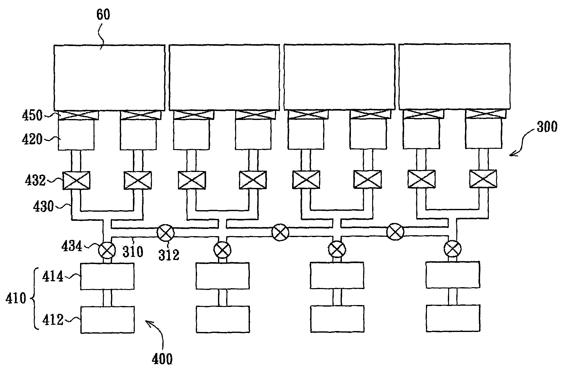
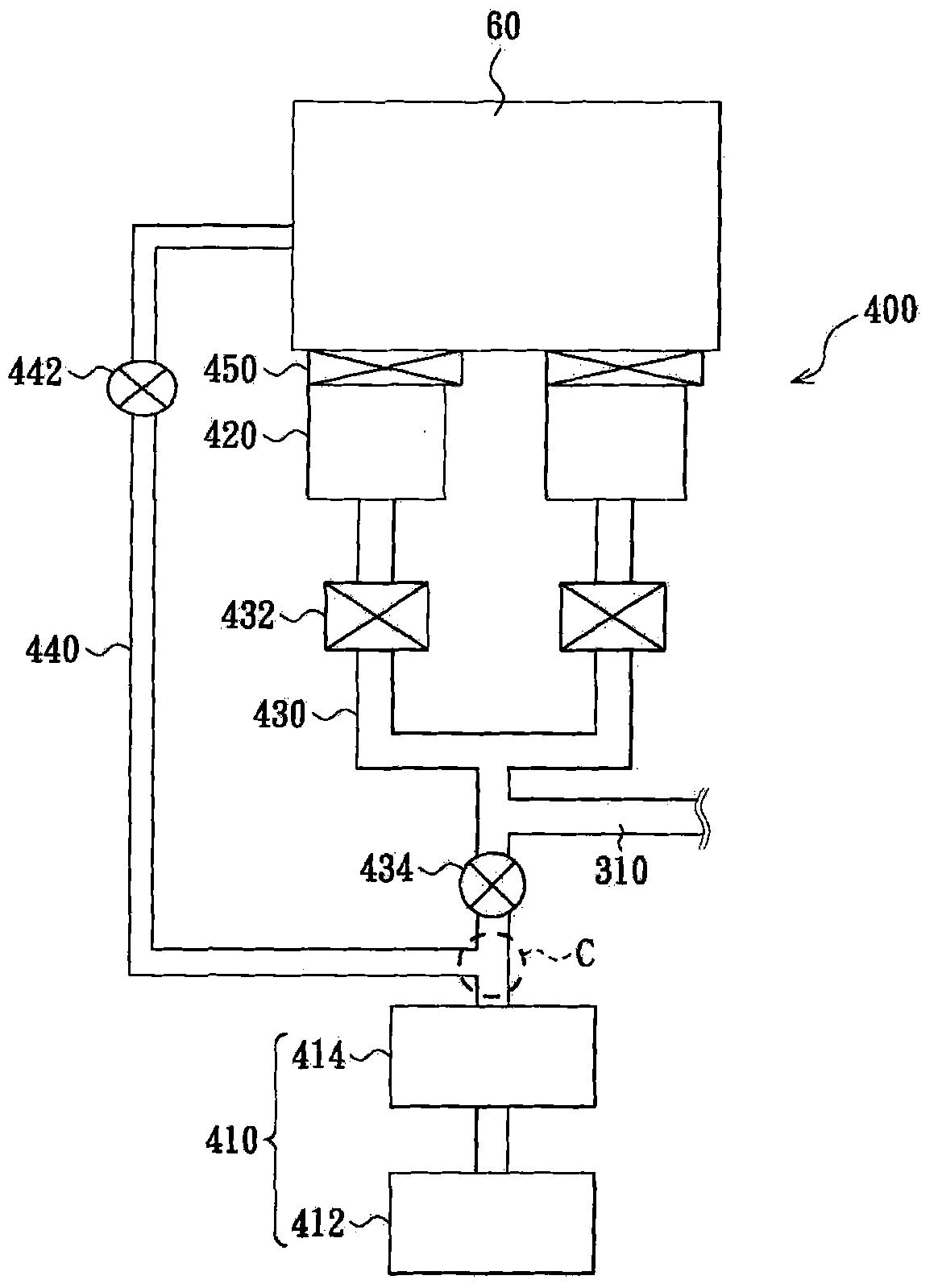
[0051] figure 2 is a schematic diagram of a vacuum device according to an embodiment of the present invention, wherein figure 2 The second line unit of each pumping unit is omitted. image 3 yes figure 2 Schematic diagram of a single pumping unit in . Please refer to figure 2 and image 3 , the vacuum device 300 of this embodiment is suitable for providing a vacuum environment in the plurality of chambers 60 . The vacuum device 300 includes a plurality of air extraction units 400 and a third pipeline unit 310 . Each pumping unit 400 is connected to one of the plurality of chambers 60, and each pumping unit 400 includes a low vacuum pumping device 410, at least one high vacuum pumping device 420 ( figure 2 Take two high vacuum pumping devices 420 as an example), the first pipeline unit 430 and the second pipeline unit 440 . The high vacuum pumping device 420 is disposed between the low vacuum pumping device 410 and the corresponding chamber 60 , and is connected to ...


PUM


Abstract

The invention relates to a vacuum device which is suitable for vacuum environment providing a plurality of cavities. The vacuum device comprises a plurality of pumping units and a third pipeline unit, wherein each pumping unit is connected to one cavity and comprises a low vacuum pumping device, at least one vacuum pumping device, a first pipeline unit and a second pipeline unit. A high vacuum pumping device is arranged between the low vacuum pumping device and a corresponding cavity; the first pipeline unit is connected to the high and low vacuum pumping devices and is provided with at least a first valve; the second pipeline unit is connected to a corresponding cavity and the first pipeline unit and is provided with a second valve; the joint of the second pipeline unit and the first pipeline unit is positioned between the first valve and the low vacuum pumping device; the second pipeline unit is connected to the first pipeline unit; and the third pipeline unit is provided with at least a third valve arranged between the adjacent first pipeline units.

Description

technical field [0001] The present invention relates to an air extraction device, and in particular to a vacuum device. Background technique [0002] figure 1 It is a schematic diagram of a vacuum device in the prior art. Please refer to figure 1 , the prior art vacuum equipment 100 includes a plurality of independent air pumping units 200 . Each pumping unit 200 is used to provide a vacuum environment in the chamber 50 . Each air extraction unit 200 includes a dry pump (dry pump) 210, a booster pump (booster pump) 220 and two turbo pumps (booster pump) 230, wherein the booster pump 220 is connected to the dry pump 210 and the turbo pump 230 between. The turbo pump 230 is connected to the corresponding chamber 50 , and a valve element 240 is disposed between the turbo pump 230 and the chamber 50 . The turbo pumps 230 are connected to the boost pump 220 through the pipeline unit 250 , and a valve 260 is provided between each turbo pump 230 and the boost pump 220 . In a...

Claims


Application Information

Patent Timeline
Patent Type & Authority Applications(China)
IPC IPC(8): F04B37/14
Inventor 徐弘迪吴仲尧陈振维王春盛张皓岚
Owner AU OPTRONICS CORP
Why Eureka
Try Eureka