Centrifugal lint trap

a centrifugal lint trap and filter technology, applied in the field of filters, can solve the problems of many homes, apartments and condominiums without ductwork, and achieve the effects of improving efficiency, increasing efficiency, and improving lint collection efficiency

Inactive Publication Date: 2005-11-17
TYAU WARREN
View PDF4 Cites 24 Cited by
  • Summary
  • Abstract
  • Description
  • Claims
  • Application Information

AI Technical Summary

Benefits of technology

[0004] The present invention includes a conical chamber which improves the efficiency of lint collection by inducing a swirling action to the air stream, thereby creating a centrifugal force which greatly increases the efficiency of lint collection. As a result of this increased efficiency, the air quality in the living areas is greatly improved. The present invention requires no moving parts and does not require an external power source. The present invention is easy to clean and maintain and can be mounted on the wall for easy access. The lint trap of the present invention generates a gentle swooshing sound, which is a result of the swirling of water which may be audible as the exhaust air flows through the conical collection chamber. The lint trap of the present invention effectively utilizes water and moisture condensation as a surfactant to trap airborne particles ducted through the collection chamber. This centrifugal action compresses the air slightly and results in a moderate increase in velocity. The compression causes the airborne particles to coalesce through inertia impaction (liquid and particle) or Brownian diffusion (particle and particle). The resulting centrifugal force pushes the coalesced particles into the wetted walls of the chamber and the free surface of the water, completing the air scrubbing process and providing substantially lint free air to be exhausted from the filter. To further increase the filter's efficiency, a removable / washable, internal cylindrical filter screen acts to trap lint particles against the side of the conical collection chamber. The cylindrical filter screen is not a “flow through” or “pass through” filter. Unlike pass through filters which increase back pressure when a heavy layer of dirt / lint has accumulated, a cylindrical internal filter screen will not cause an increase in dryer exhaust back pressure as lint begins to deposit on the filter screen.
[0005] The lint filter of the present invention uses ordinary tap water or any other suitable liquid as a surficant. This provides an inexpensive filter medium. The lint filter of the present invention will not substantially reduce or restrict dryer exhaust airflow rate and will not degrade dryer efficiency.

Problems solved by technology

Additionally, many homes, apartments and condominiums do not have the ductwork to duct the outlet for the clothes dryers to the outside.
The problem with these types of clothes dryers is that the internal filter screen does not remove all of the lint that is exhausted from the clothes dryer.

Method used


Image

  • Centrifugal lint trap
  • Centrifugal lint trap
  • Centrifugal lint trap

Examples


Embodiment Construction

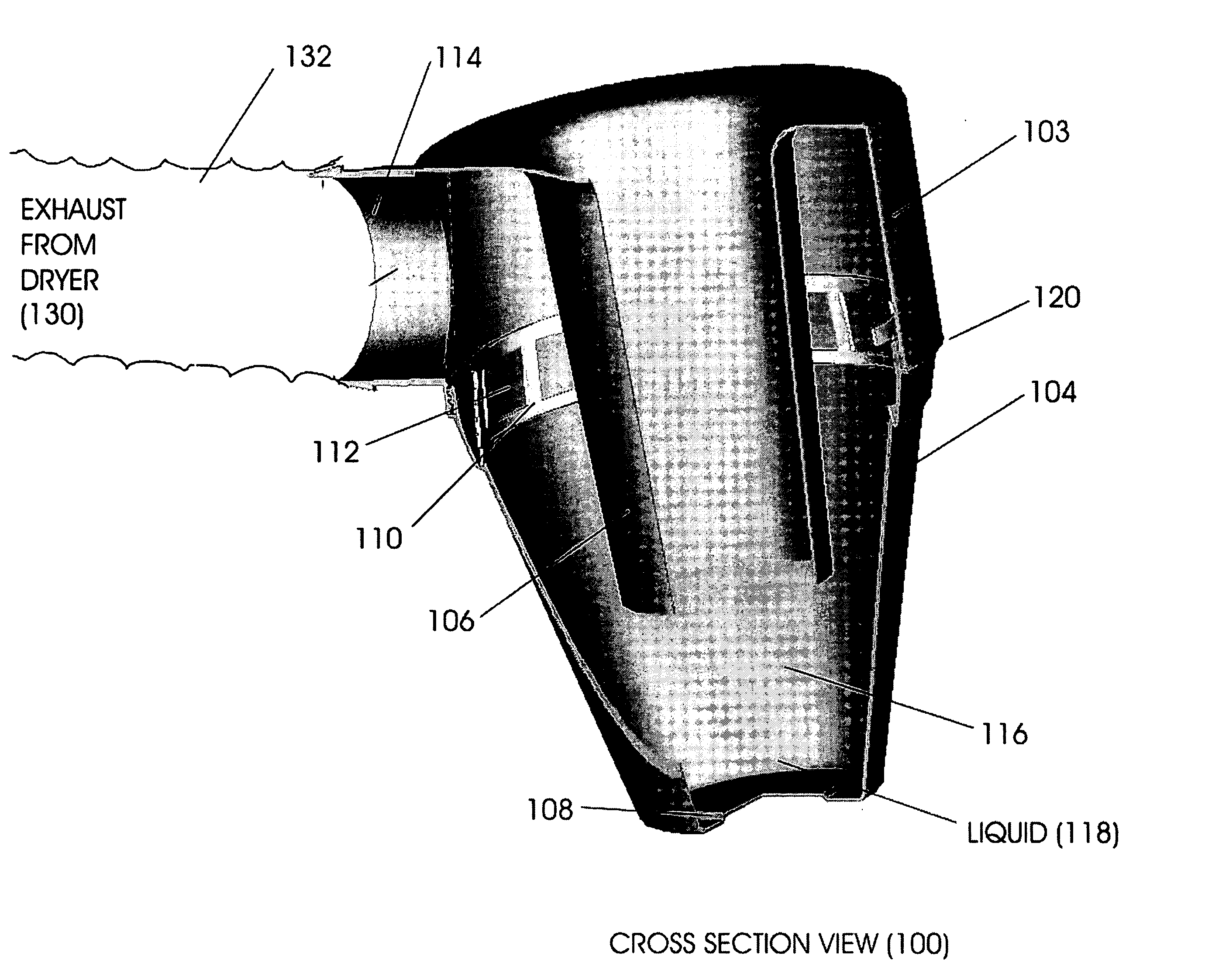
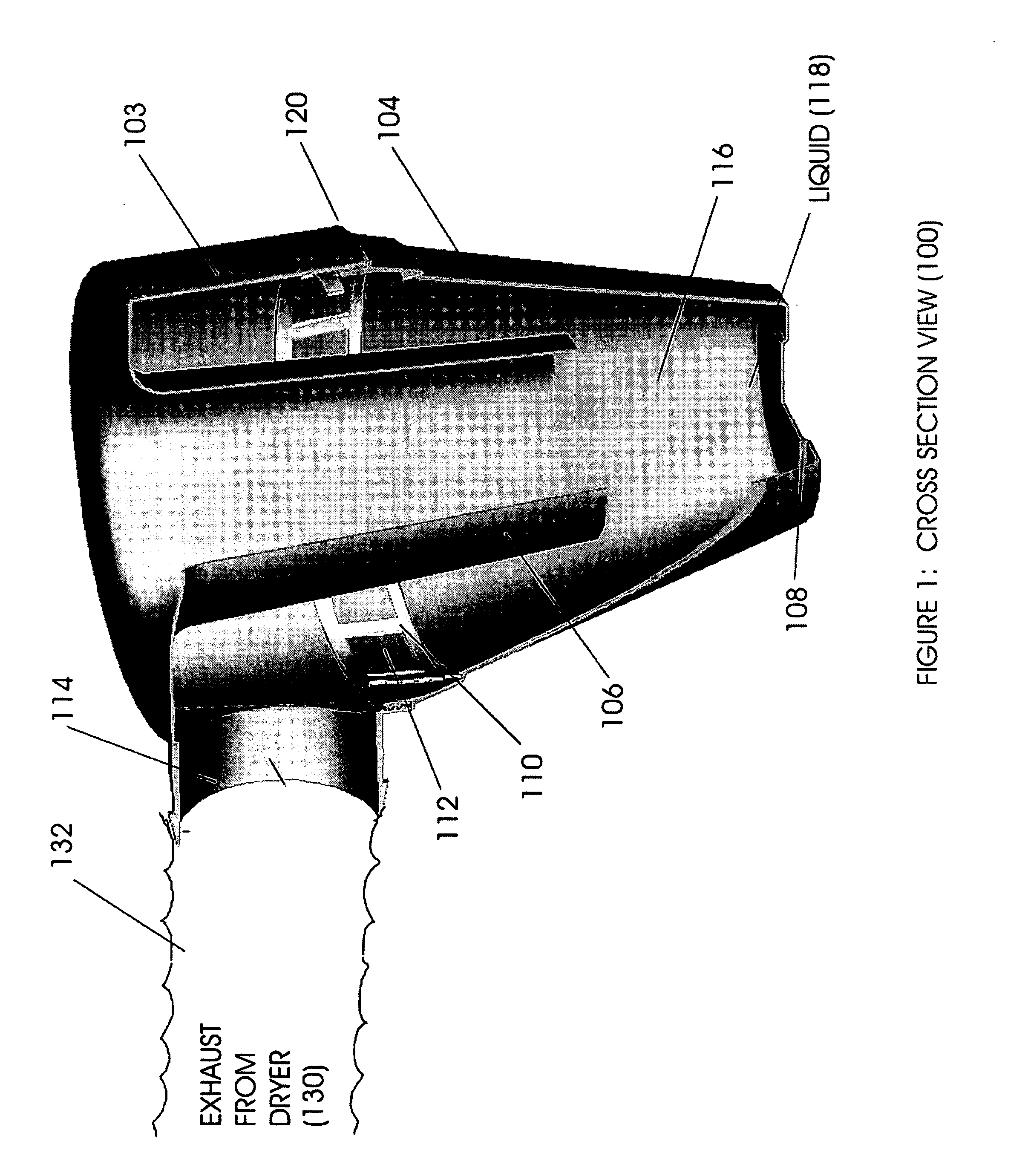
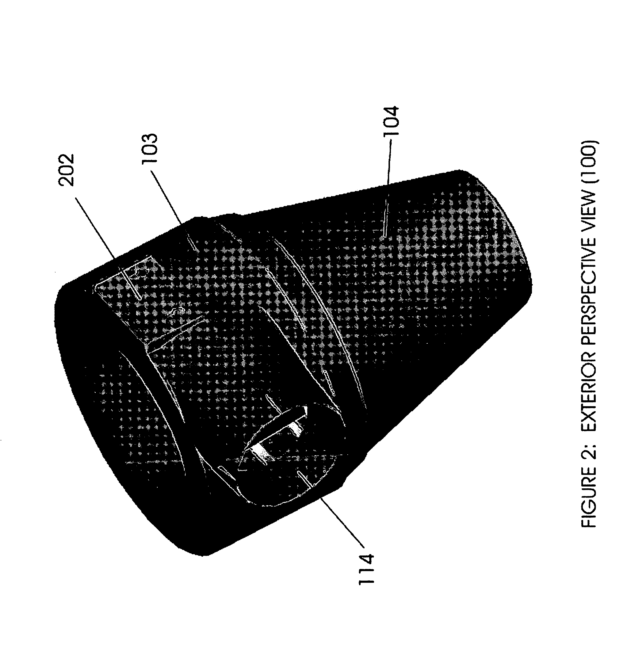
[0010]FIG. 1 illustrates the lint trap 100 which includes a collection chamber 116 and an air inlet fitting 114. The collection chamber 116 includes an outer hollow housing 102 which includes an upper housing 103 and a conical base 104, and tapered inner tube 106. A liquid 118 for example water or any other suitable liquid is placed in the bottom of the removable base 104. The upper housing 103 is substantially a cylinder and is formed with or attached to the air inlet fitting 114 for attachment to clothes dryer 130 through an appropriate tubing 132. The removable base 104 has a tapered gradient to compress the air and increase the velocity of the air as it travels down the tapered gradient. This compression of the air causes the airborne particles such as lint to coalesce through inertial impaction (liquid and particle) or Brownian diffusion (particle and particle). The resulting centrifugal force pushes the coalesced particles into the wetted walls and / or the cylindrical inner scr...


PUM


Abstract

A lint trap for trapping air particles includes an air inlet for allowing the air particles to enter the lint trap and a base having a tapered gradient for increasing the velocity of the air particles and containment by centrifugal force. The air inlet is connected to a dryer.

Description

PRIORITY [0001] The present application claims priority under 35 USC section 119 based upon application Ser. No. 60 / 571, 647 filed on May 17, 2004.FIELD OF THE INVENTION [0002] The present invention relates to filters and more particularly to lint filters used with clothes dryers. BACKGROUND OF THE INVENTION [0003] In clothes dryers of the type having a rotatable drum through which heated or unheated air is forced to flow to dry clothes, lint removal usually includes a filter positioned in or adjacent to the outlet for air from the clothes dryer. Additionally, many homes, apartments and condominiums do not have the ductwork to duct the outlet for the clothes dryers to the outside. The only alternative is to have the clothes dryer vent the output from the clothes dryer into the living area. The consequence of this type of ducting is that the living areas are saturated with the lint that is not trapped by the internal filter screen. The problem with these types of clothes dryers is th...

Claims


Application Information

Patent Timeline
Patent Type & Authority Applications(United States)
IPC IPC(8): D06F58/22F26B11/02F26B21/06F26B25/00
CPCF26B25/007D06F58/22
Inventor TYAU, WARREN
Owner TYAU WARREN
Why Eureka
Try Eureka