Disposable, High Pressure Microfluidic Chips

a microfluidic chip, high-pressure technology, applied in the field of microfluidic devices, can solve the problems of impeded broader use of microfluidics, slow and expensive fabrication, lack of standard interconnects for interfacing the macroscale environment with microfluidic channels within the chip,

Inactive Publication Date: 2011-12-08
RGT UNIV OF CALIFORNIA
View PDF16 Cites 24 Cited by
  • Summary
  • Abstract
  • Description
  • Claims
  • Application Information

AI Technical Summary

Problems solved by technology

However, fabrication is both slow and expensive, as it involves a multi-step process consisting of cleaning, photoresist deposition, lithography, and etching.
An obstacle that currently impedes broader use of microfluidics is the lack of standard interconnects for interfacing the macroscale environment with microfluidic channels within a chip.
Unfortunately, this manual

Method used


Image

  • Disposable, High Pressure Microfluidic Chips
  • Disposable, High Pressure Microfluidic Chips
  • Disposable, High Pressure Microfluidic Chips

Examples


Embodiment Construction

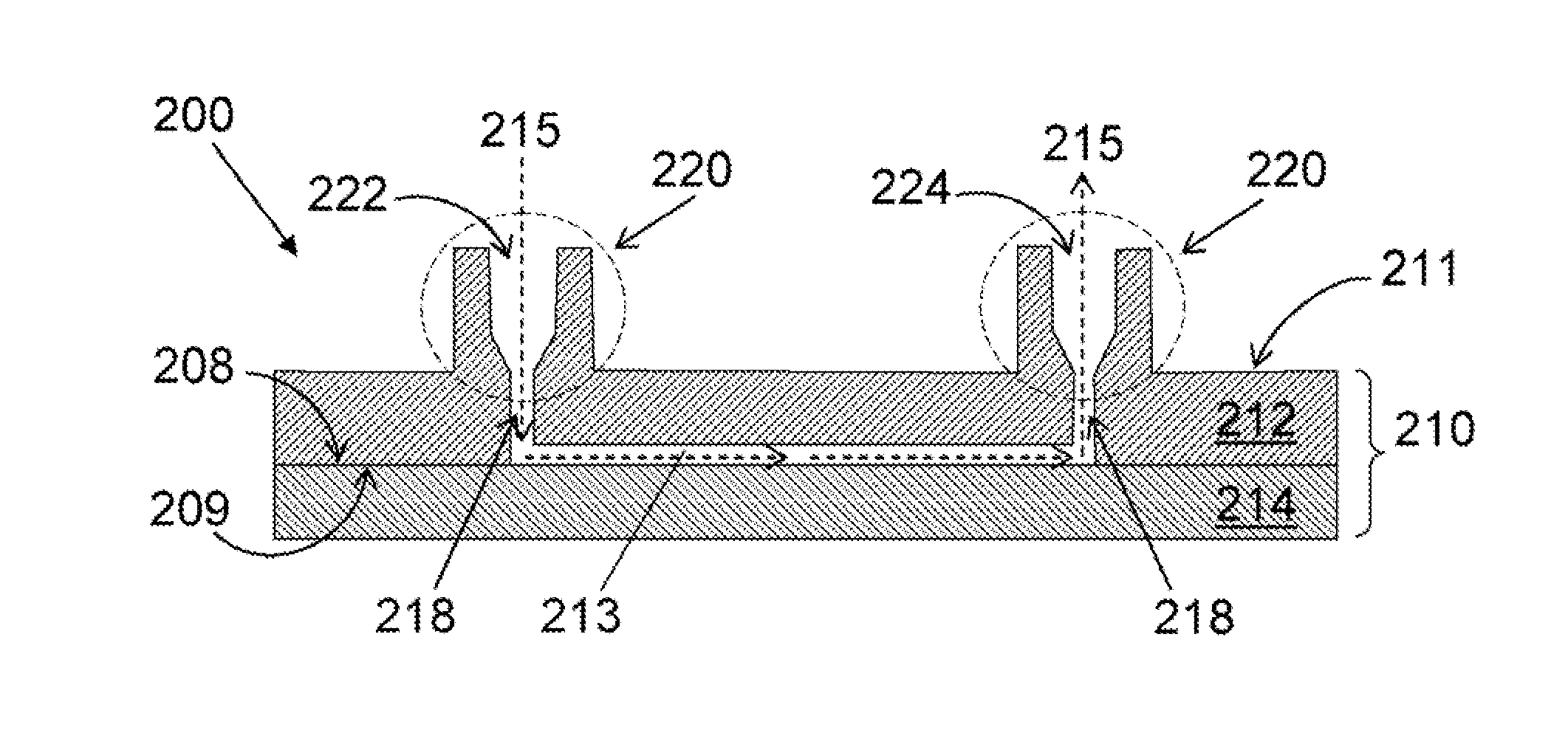
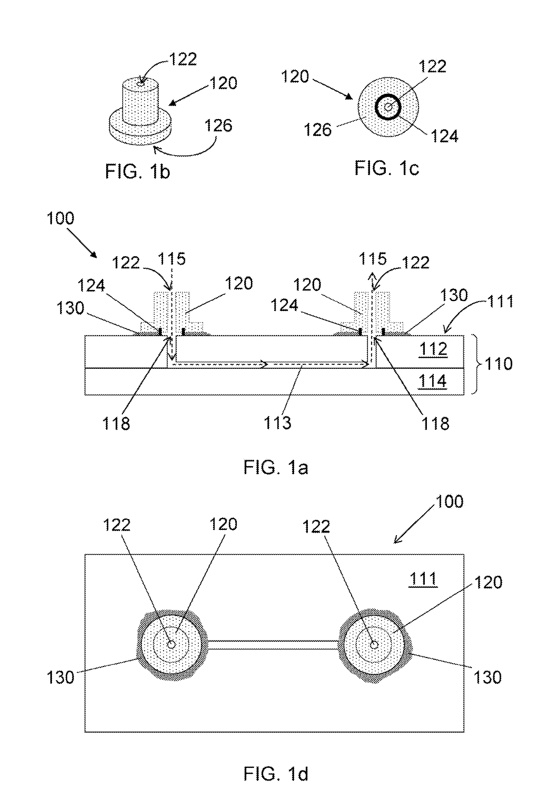
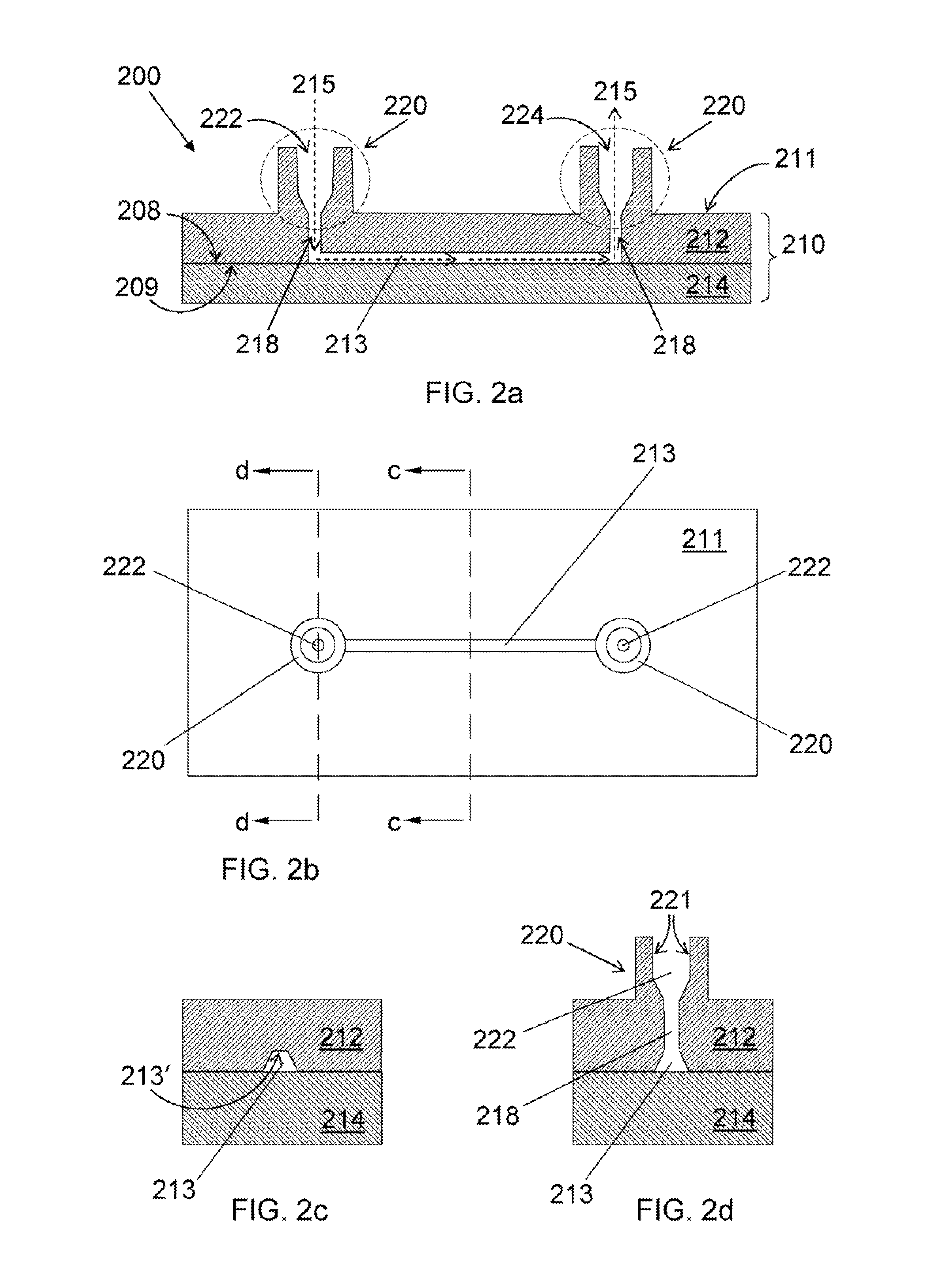
[0008]An injection molding process for the fabrication of disposable unitary plastic microfluidic chips with a cycle time on the order of minutes is described in the embodiments of the invention herein. The microfluidic chips feature novel, integrated, reversible, standardized, ready-to-use interconnects that enable operation at pressures not before realized with microfluidic chips.

[0009]The microfluidic chip as described herein has integrated interconnects and offers many desirable benefits. Each individual port has a very small footprint, thus allowing a high density of fluidic I / O ports on a single chip. The ports are configured to have minimal dead volume, which allows more efficient use of analytes and less concern that important materials have gotten trapped in the port instead of flowing into the analytical portion of the chip. The chip with integrated interconnects is easy to use. There is no need to develop great skill in positioning and gluing ports onto a chip. And there ...


PUM

PropertyMeasurementUnit
Timeaaaaaaaaaa
Pressureaaaaaaaaaa
Surface areaaaaaaaaaaa

Abstract

An injection molding process for the fabrication of disposable unitary plastic microfluidic chips with a cycle time on the order of minutes is described. The microfluidic chips feature novel, integrated, reversible, standardized, ready-to-use inter-connects that enable operation at pressures not before realized with microfluidic chips.

Description

CROSS-REFERENCE TO RELATED APPLICATIONS[0001]This application claims priority to U.S. Provisional Patent Application 60 / 805,155 filed Jun. 19, 2006, which is incorporated by reference herein.STATEMENT OF GOVERNMENTAL SUPPORT[0002]The invention described and claimed herein was made in part utilizing funds supplied by the U.S. Department of Energy under Contract No. DE-ACO3-76SF00098, and more recently under DE-ACO2-05CH11231. The government has certain rights in this invention.TECHNICAL FIELD[0003]This invention relates generally to microfluidic devices, and, more specifically, to a microfluidic chip with integrated interconnects and a method of making same.BACKGROUND ART[0004]Portable and self-contained point-of-care diagnostic tools are the promise of miniaturized biomedical analysis devices—microfluidics. Efforts to scale-down chemical analyses with microfluidic devices have been driven by the significant reduction in the volume of reagents and samples required for analysis as wel...

Claims


Application Information

Patent Timeline
IPC IPC(8): B01L99/00B29C45/16
CPCB29C66/92443B29C66/91943B01L3/502707B01L3/502715B01L3/565B01L2200/027B01L2200/12B01L2300/0816B01L2300/0838B29C45/0053B29C45/2628B29C65/02B29C65/18B29C65/4895B29C65/8246B29C66/54B29C66/919B29C66/949B29C2045/0094B29K2105/0085B29K2909/08B29L2031/756B81B7/0006B81B2201/058B81C2201/034B29C65/8253B29C66/5346B29C66/91431B29C66/962B29C66/966B29C65/48B29C66/9192B29C66/92921B29C66/1122B29C66/71B29K2023/38
Inventor MAIR, DIEUDONNEGEIGER, EMIL J.
Owner RGT UNIV OF CALIFORNIA
Why Eureka
Try Eureka