Gas flow enhancer for combustion engines

a technology of gas flow enhancer and combustion engine, which is applied in the direction of combustion engine/fuel air treatment, machines/engines, mechanical equipment, etc., can solve the problems of reducing the life of lubricants and the engine itself, reducing the power output and efficiency of the engine, and increasing the operating temperature of the engine, so as to reduce the noise of the engine and increase the back pressure on the engin

Inactive Publication Date: 2006-04-13
FREEDMAN LEN
View PDF8 Cites 22 Cited by
  • Summary
  • Abstract
  • Description
  • Claims
  • Application Information

AI Technical Summary

Benefits of technology

[0008] It has been recognized that it would be advantageous to develop an exhaust system that can reduce engine noise without substantially increasing back pressure on the engine.

Problems solved by technology

Unfortunately, these components disposed in the exhaust stream tend to increase exhaust back pressure, thus reducing the power output and efficiency of the engine.
This also tends to result in a higher operating temperature for the engine, reducing the life of lubricants and of the engine itself.

Method used


Image

  • Gas flow enhancer for combustion engines
  • Gas flow enhancer for combustion engines
  • Gas flow enhancer for combustion engines

Examples


Embodiment Construction

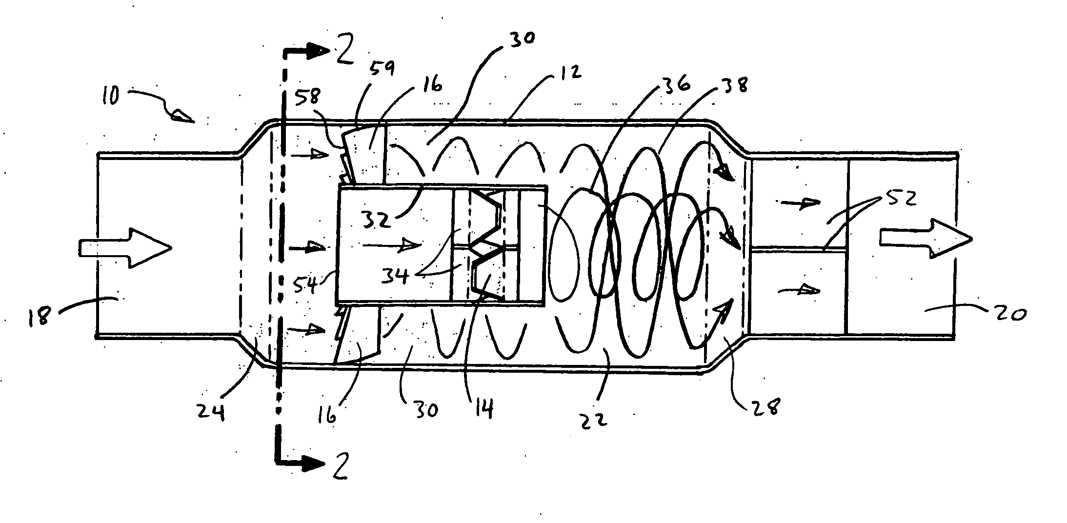
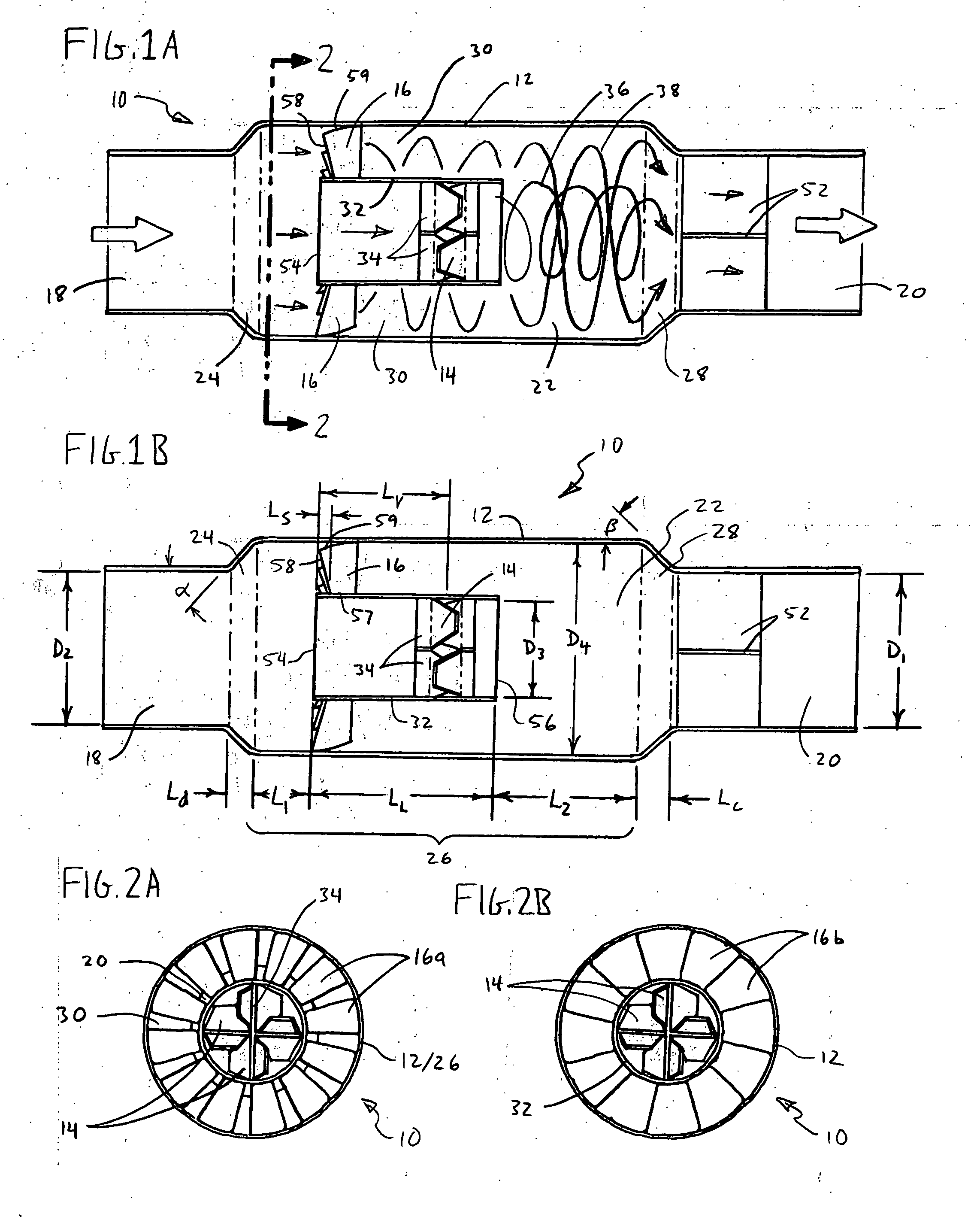
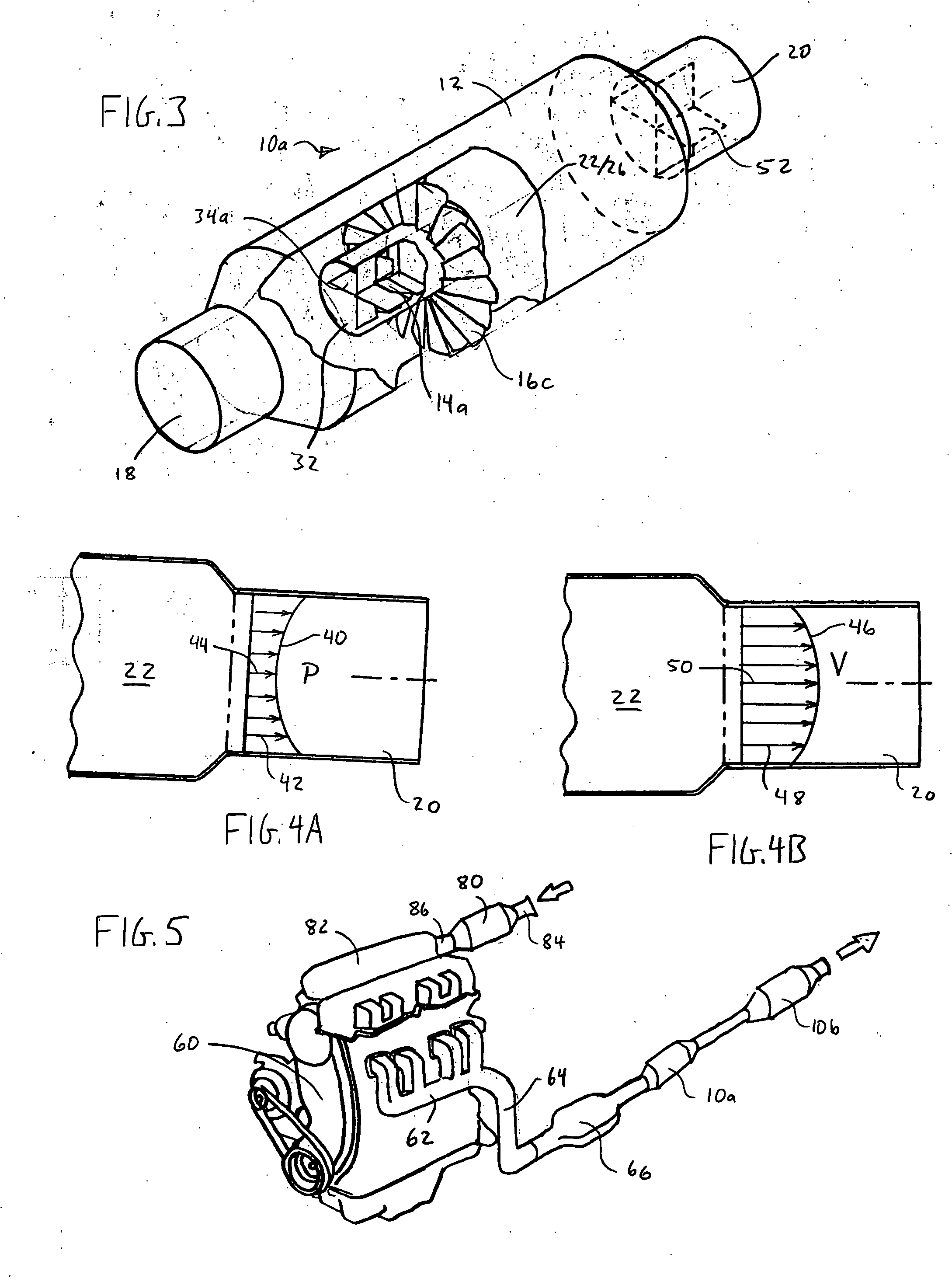
[0032] Reference will now be made to the exemplary embodiments illustrated in the drawings, and specific language will be used herein to describe the same. It will nevertheless be understood that no limitation of the scope of the invention is thereby intended. Alterations and further modifications of the inventive features illustrated herein, and additional applications of the principles of the invention as illustrated herein, which would occur to one skilled in the relevant art and having possession of this disclosure, are to be considered within the scope of the invention.

[0033] The present invention provides a device for enhancing the flow of gasses in a conduit associated with a combustion engine. As used herein, the term “gas” is intended to have its basic scientific meaning—i.e. a fluid that is not a liquid. The device of the present invention is applicable to both exhaust gasses and inlet gasses for an engine, and reduces overall flow pressure, and increases velocity, for gr...


PUM


Abstract

A gas flow enhancer for a combustion engine includes a housing, configured to receive an inlet flow of gas at an inlet pressure, and enclosing an expansion chamber. Disposed within the expansion chamber are a set of inner vanes and outer vanes, and a flow separator. The outer vanes are disposed outside the flow separator and produce an outer helical flow of the gas. The inner vanes are disposed within the flow separator and produce an inner helical flow of the gas, the inner helical flow having a higher velocity and lower pressure than the outer helical flow. The outer helical flow and inner helical flow are recombined at an outlet of the expansion chamber so as to produce an outlet laminar flow profile having a lower average pressure than the inlet pressure.

Description

PRIORITY CLAIM [0001] The present application claims priority from U.S. provisional patent application Ser. No. 60 / 580,146, filed Jun. 15, 2004, and entitled PIETO TURBORAMJET ENGINE COOLER AND MUFFLER.BACKGROUND OF THE INVENTION [0002] 1. Field of the Invention [0003] The present invention relates generally to gas flow in combustion engines. More particularly, the present invention relates to a device for improving the efficiency of gas flow in an intake or exhaust conduit, so as to increase engine power and efficiency. [0004] 2. Related Art [0005] The principles of operation of combustion engines are well understood. Air and fuel are mixed and drawn into a combustion chamber through inlet valves, where they are ignited. The ignition imparts kinetic energy to mechanical engine components, allowing the engine to do work, and also produces hot waste gasses which are discharged through exhaust valves, and eventually exhausted to the atmosphere. [0006] In order for the engine to do wor...

Claims


Application Information

Patent Timeline
Patent Type & Authority Applications(United States)
IPC IPC(8): F01N3/00F02B35/00
CPCF01N1/088F01N3/0892F01N3/36F01N3/38Y02T10/20Y02T10/12F01N3/2033F01N3/26F02M35/10006
Inventor CUMMINGS, CRAIG D.
Owner FREEDMAN LEN
Why Eureka
Try Eureka