
Auxiliary device for manufacturing cable head

An auxiliary device and cable head technology, which is used in equipment for disassembling/armored cables, equipment for connecting/terminating cables, metal processing, etc., can solve the problems of poor cable head consistency, uneven trimming, laborious operation, etc. To achieve the effect of reducing labor intensity, convenient and quick assembly and disassembly, and improving quality

Active Publication Date: 2010-12-22
STATE GRID CHONGQING ELECTRIC POWER COMPANY SKILLTRAINING CENT +1
View PDF8 Cites 19 Cited by
  • Summary
  • Abstract
  • Description
  • Claims
  • Application Information

AI Technical Summary

Problems solved by technology

[0002] At present, in the production site of power cable head production, various special stripping cutters are mainly used to strip and cut the cable sheath. It is necessary to manually control the direction of the stripping cutter and the stripping depth. There is no special cable positioning mechanism and stripping depth control. Mechanism, usually first draw and print on the cable, and then manually use a stripping knife to peel and cut, the operation is laborious and the efficiency is low
Moreover, since the direction of the stripping cutter and the depth of stripping are mainly controlled by the experience of the operator, the stripping size is inaccurate, the cutting edge is not neat, and the consistency of the produced cable head is poor, which affects the production quality of the cable head.

Method used


Image

  • Auxiliary device for manufacturing cable head
  • Auxiliary device for manufacturing cable head
  • Auxiliary device for manufacturing cable head

Examples


Embodiment Construction

[0026] The present invention will be further described below in conjunction with drawings and embodiments.

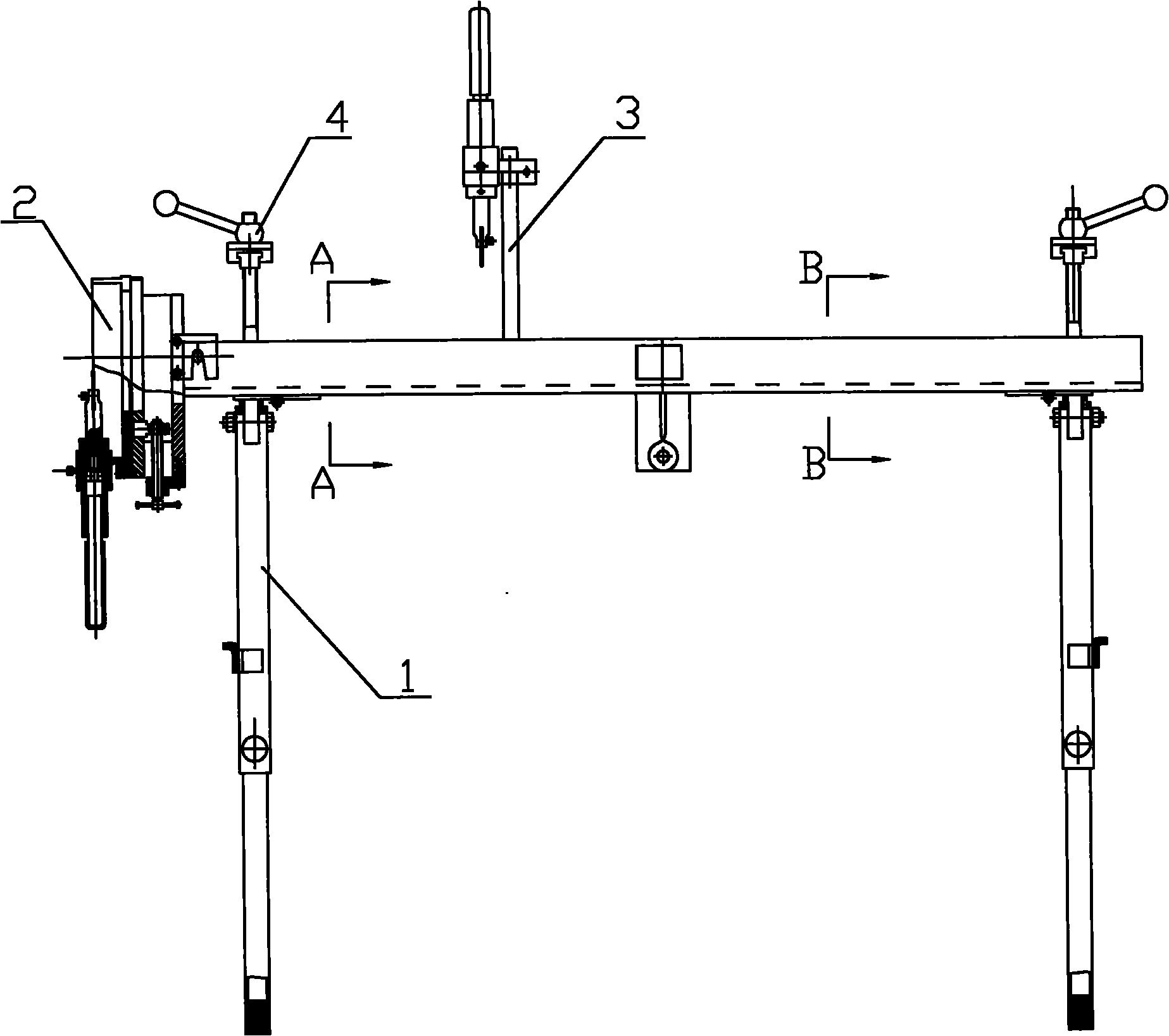
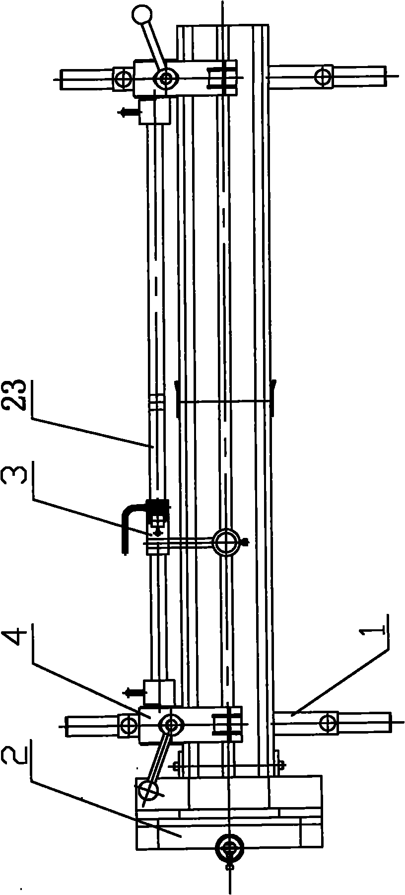
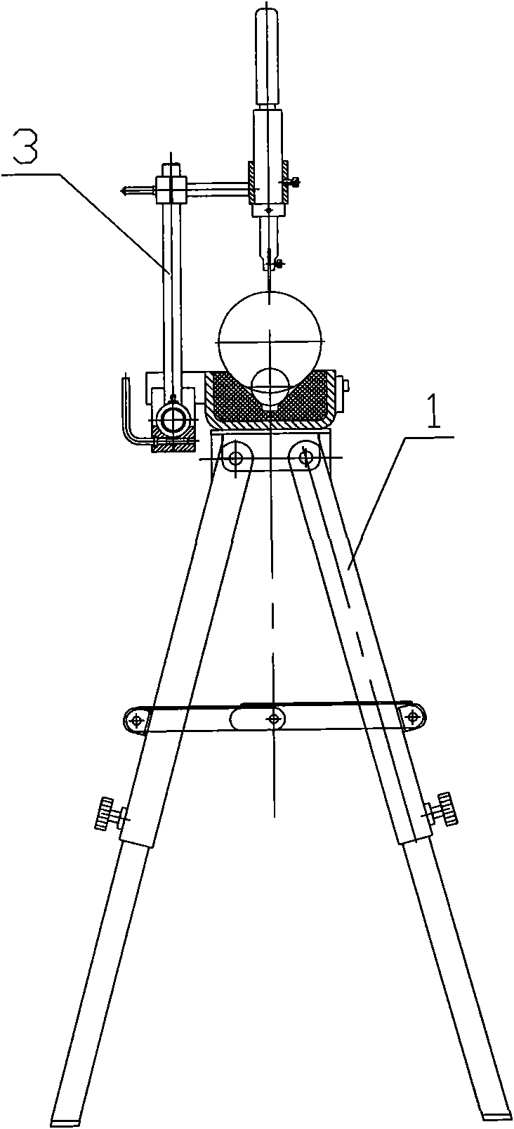
[0027] like Figure 1 to Figure 4 As shown, the auxiliary device for making cable heads according to the present invention has a frame 1 and a rotary cutting mechanism 2 , a linear cutting mechanism 3 and a pressing mechanism 4 installed on the frame 1 . The rotary cutting mechanism 2 is used to realize radial stripping and cutting of the cable sheath, the linear cutting mechanism 3 is used to realize axial stripping and cutting of the cable sheath, and the pressing mechanism 4 is used to compress and position the cable on the frame 1 superior. figure 2 , image 3 The double dotted line circle in the middle represents the outer contour of the cable line.

[0028] see Figure 5 to Figure 8 . The frame has support legs 5 and a worktable 6 hinged on the support legs 5, and the two support legs 5 at the same end of the workbench 6 can be folded together.

[0029] The...


PUM


Abstract

The invention provides an auxiliary device for manufacturing a cable head, comprising a stand, a rotary cutting mechanism, a linear cutting mechanism and a press mechanism, wherein the stand is provided with support legs and a working table plate articulated with the support legs; the working table plate is provided with a cable wire placing groove along a length direction; a rotary cutting tool rest is arranged at one end of the working table plate; a linear cutting tool rest is arranged on a linear sliding rail; the linear sliding rail is connected to a working table plate side and parallel to the working table plate; the press mechanism is provided with a supporting seat and a press plate arranged on the supporting seat; the supporting seat is connected to the side surface of the working table plate; and the press plate is provided with a pressing wire groove opposite to the cable wire placing groove positioned on the working table plate up and down. The auxiliary device is used for completing the fast striping and cutting of a cable wire protective layer during the manufacture of the cable head and accurately controlling the striping and cutting length and depth of the cable wire protective layer, thereby enhancing the manufacturing quality of the cable head and reducing the labor intensity of operators; in addition, the auxiliary device is portable after be folded, has convenient and fast assembly and disassembly of parts and is very suitable for being used as a striping and cutting tool on a manufacturing site of the cable head.

Description

technical field [0001] The invention relates to a tool for making a power cable head, in particular to a device for stripping and cutting the cable sheath when making a power cable head. Background technique [0002] At present, in the production site of power cable head production, various special stripping cutters are mainly used to strip and cut the cable sheath. It is necessary to manually control the direction of the stripping cutter and the stripping depth. There is no special cable positioning mechanism and stripping depth control. Mechanisms usually first draw and print on the cable, and then manually use a stripping knife to peel and cut, which is laborious and inefficient. And because mainly rely on the experience of the operator to control the direction of the stripping cutter and the depth of stripping, the stripping size is inaccurate, the trimming is not neat, and the consistency of the produced cable head is poor, which affects the production quality of the ca...

Claims


Application Information

Patent Timeline
IPC IPC(8): H02G1/14H02G1/12B26D1/14
Inventor 彭长均向平于鹏何勇夏冰袁永萍唐继跃敬勇谭晓玉谢维兵康成林杨旭姚曙明简泉
Owner STATE GRID CHONGQING ELECTRIC POWER COMPANY SKILLTRAINING CENT
Features
  • Generate Ideas
  • Intellectual Property
  • Life Sciences
  • Materials
  • Tech Scout
  • Unparalleled Data Quality
  • Higher Quality Content
  • 60% Fewer Hallucinations
Learn More