Current equalizing structure of high-current rectifier bridge arm
A technology of rectifiers and rectifier bridges, applied in the direction of electrical components, output power conversion devices, etc., can solve the problems of quantitative analysis with few bridge arms, stay in qualitative analysis, and it is difficult to propose accurate and effective improvement methods, so as to achieve imbalance The situation is reduced and the effect of good current equalization effect
Inactive Publication Date: 2010-12-22
INST OF PLASMA PHYSICS CHINESE ACAD OF SCI
View PDF4 Cites 5 Cited by
- Summary
- Abstract
- Description
- Claims
- Application Information
AI Technical Summary
Problems solved by technology
[0003] However, for a long time, few people have made a quantitative analysis of the reasons for the current imbalance of the bridge arm, only staying at the level of qualitative analysis
Therefore, it is difficult to propose accurate and effective improvement methods
Method used
View moreImage
Smart ImageViewing Examples
Examples
Embodiment Construction
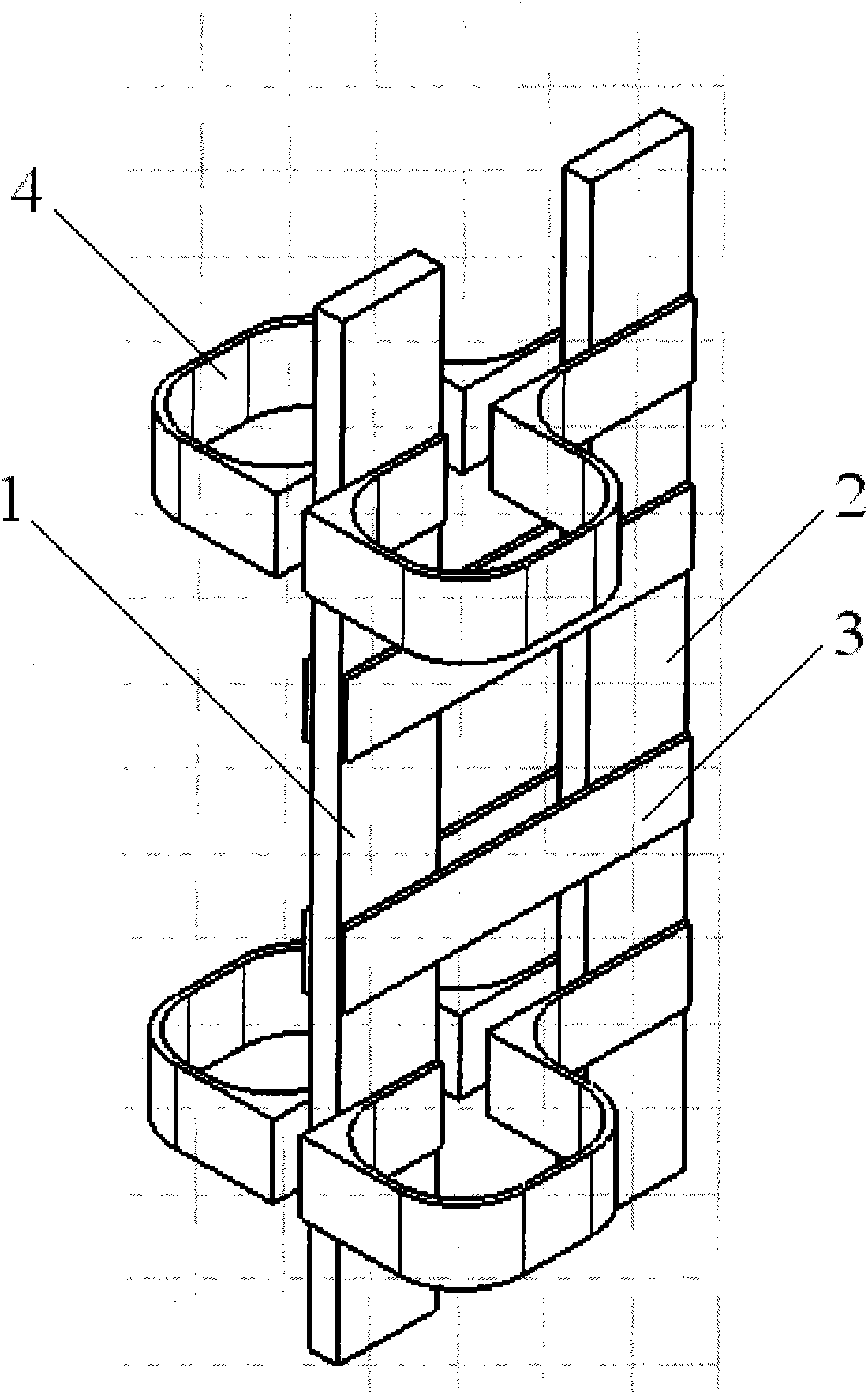
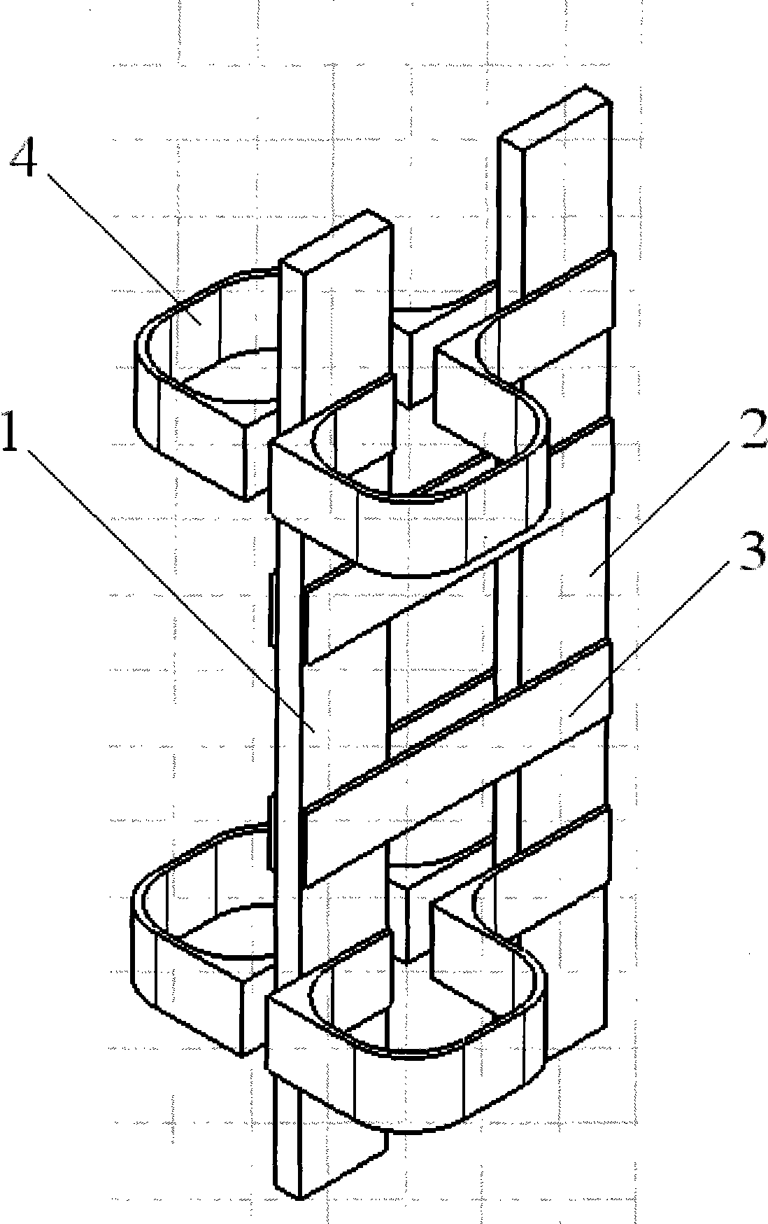
[0010] see figure 1 , a current sharing structure of a large current rectifier bridge arm, including left and right rectifier bridge arms 1, 2, the front and rear of the left and right rectifier bridge arms 1, 2 are respectively fixedly connected with several connecting busbars from top to bottom 3, wherein one end 4 of the connecting busbar located at the upper and lower ends is respectively bent outward.
Login to View More PUM
 Abstract
The invention discloses a current equalizing structure of a high-current rectifier bridge arm, comprising a left rectifying bridge arm and a right rectifying bridge arm, wherein the front sides and the right sides of the left rectifying bridge arm and the right rectifying bridge arm are respectively and fixedly connected with a plurality of connecting busbars from top to bottom, and one ends of the connecting busbars at the upper end and the lower end are respectively outwards bent. In the invention, one ends of the connecting busbars at the upper end and the lower end are respectively outwards bent, i.e. the lengths of the connecting busbars at the upper end and the lower end are increased, and the unbalanced condition of the whole rectifying bridge arm current is reduced, thereby a good current equalizing effect is achieved.
Description
technical field [0001] The invention relates to a current sharing structure of a bridge arm of a large current rectifier. Background technique [0002] Generally speaking, the connecting bus bars of the rectifier bridge arm are of equal length, resulting in the asymmetry of the bridge arm structure. Therefore, in the application of high current, the current between the parallel components in the bridge arm is very uneven. , so that some components are in an overload state for a long time, which directly affects the safety and reliability of the rectifier operation. In addition, through the improvement of the current sharing coefficient, the number of parallel elements can also be appropriately reduced to save costs. [0003] However, for a long time, few people have made a quantitative analysis of the cause of the current imbalance of the bridge arm, only staying at the level of qualitative analysis. Therefore, it is difficult to propose an accurate and effective improveme...
Claims
Login to View More Application Information
Patent Timeline
 Patent Type & Authority Applications(China)
IPC IPC(8): H02M1/00
Inventor 陈鹏傅鹏宋执权
Owner INST OF PLASMA PHYSICS CHINESE ACAD OF SCI
Features
- R&D
- Intellectual Property
- Life Sciences
- Materials
- Tech Scout
- Unparalleled Data Quality
- Higher Quality Content
- 60% Fewer Hallucinations
Learn More Browse by: Latest US Patents, China's latest patents, Technical Efficacy Thesaurus, Application Domain, Technology Topic, Popular Technical Reports.
© 2025 PatSnap. All rights reserved.Legal|Privacy policy|Modern Slavery Act Transparency Statement|Sitemap|About US| Contact US: help@patsnap.com


