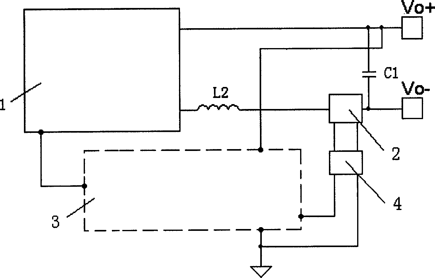
Circuit for realizing autonomous equalizing current of parallel electric source module
A technology of power module and parallel connection, which is applied in the direction of adjusting electrical variables, control/regulation systems, instruments, etc. It can solve the problems of reduced product reliability, complicated circuits, and large power consumption, and achieve simple circuits, good current sharing effects, and high power consumption. The effect of low consumption
- Summary
- Abstract
- Description
- Claims
- Application Information
AI Technical Summary
Problems solved by technology
Method used
Image
Examples
Embodiment 1
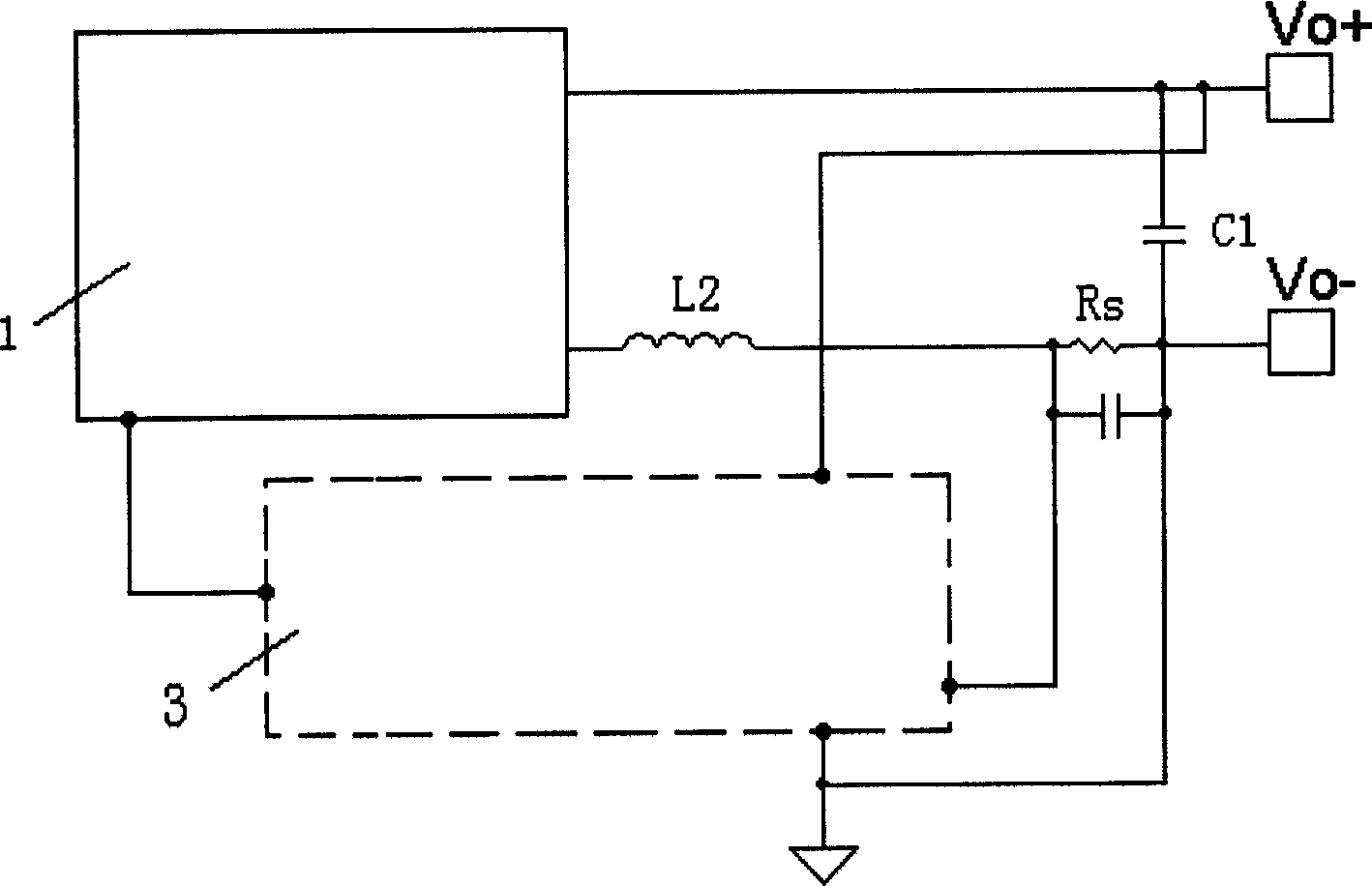
[0029] Such as Figure 5 As shown, the current sampling resistor Rs is connected in series to the negative phase output terminal Vo- of the power module, behind the output filter capacitor C1, and its low voltage terminal is connected to the negative phase output terminal Vo- of the power module. The voltage control loop 3 includes a first operational amplifier U1, a second operational amplifier U2, a first voltage dividing resistor Ra, a second voltage dividing resistor Rb, a first resistor R1, a second resistor R2, a third resistor R3, and a fourth resistor R4, the fifth resistor R5 and the reference regulator UZ. After the first voltage dividing resistor Ra and the second voltage dividing resistor Rb are connected in series, one end is connected to the positive phase output terminal Vo+ of the power module, and the other end is connected to the negative phase output terminal Vo− of the power module. The positive-phase input terminal of the first operational amplifier U1 is...
Embodiment 2
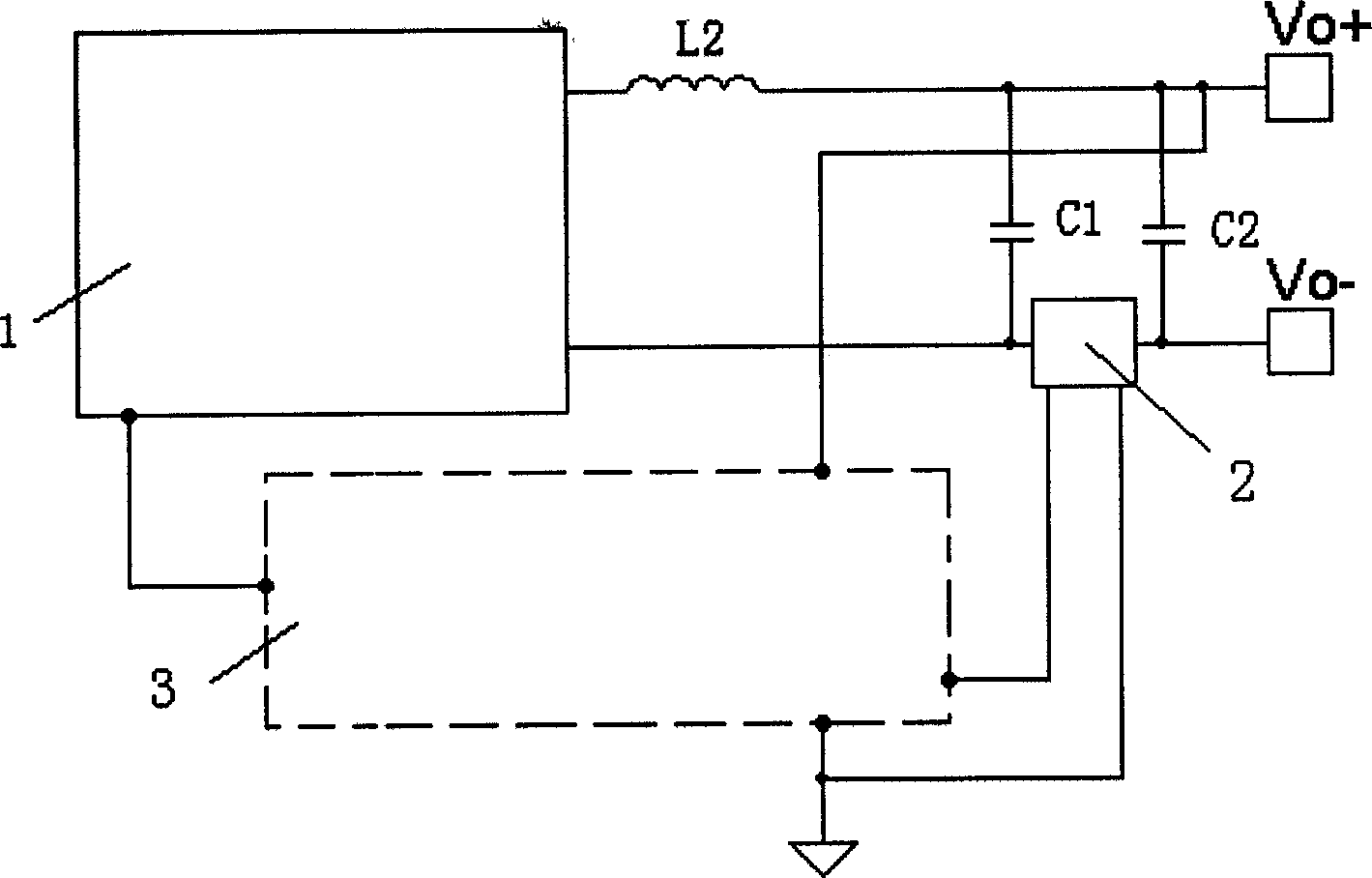
[0036] Such as Image 6As shown, the current sampling resistor Rs is connected in series to the negative phase output terminal Vo- of the power module, located between the output filter capacitors C1 and C2, and its low voltage terminal is connected to the negative phase output terminal Vo- of the power module. The voltage control loop 3 includes a first operational amplifier U1, a first voltage dividing resistor Ra, a second voltage dividing resistor Rb, a first resistor R1, a fifth resistor R5, a sixth resistor R6 and a reference regulator UZ. After the first voltage dividing resistor Ra and the second voltage dividing resistor Rb are connected in series, one end is connected to the positive phase output terminal Vo+ of the power module, and the other end is connected to the negative phase output terminal Vo− of the power module. The non-inverting input terminal of the first operational amplifier U1 is connected to the cathode of the reference voltage regulator UZ through th...
Embodiment 3
[0042] Such as Figure 7 As shown, the current sampling resistor Rs is connected in series to the negative phase output terminal Vo- of the power module, located between the output filter capacitors C1 and C2, and its low voltage terminal is connected to the negative phase output terminal Vo- of the power module. The voltage control loop 3 includes a first operational amplifier U1, a first voltage dividing resistor Ra, a second voltage dividing resistor Rb, a fifth resistor R5, a sixth resistor R6, a seventh resistor R7, an eighth resistor R8 and a reference regulator tube Uz. After the first voltage dividing resistor Ra and the second voltage dividing resistor Rb are connected in series, one end is connected to the positive phase output terminal Vo+ of the power module, and the other end is connected to the negative phase output terminal Vo− of the module. The non-inverting input terminal of the first operational amplifier U1 is connected to the negative pole of the referenc...
PUM
 Abstract
Description
Claims
Application Information
 - R&D
- Intellectual Property
- Life Sciences
- Materials
- Tech Scout
- Unparalleled Data Quality
- Higher Quality Content
- 60% Fewer Hallucinations
Browse by: Latest US Patents, China's latest patents, Technical Efficacy Thesaurus, Application Domain, Technology Topic, Popular Technical Reports.
© 2025 PatSnap. All rights reserved.Legal|Privacy policy|Modern Slavery Act Transparency Statement|Sitemap|About US| Contact US: help@patsnap.com


