Method and device for implementing uniform flow of steam in boiler barrel

A technology of steam flow, steam flow, applied in combustion method, exhaust gas device, boiler drum/box header, etc.

Active Publication Date: 2013-07-24
SHANGHAI WANGTE ENERGY RESOURCE SICENCE & TECH
View PDF5 Cites 3 Cited by
  • Summary
  • Abstract
  • Description
  • Claims
  • Application Information

AI Technical Summary

Problems solved by technology

The disadvantage of this technology and the difference from this technology is that this technology only solves the problem of sealing and steam leakage between the periphery of the steam-water separation plate and the drum, and does not involve the uneven flow of steam along the length of the upper drum. Sexuality and the problem of water surface surge in the middle of the drum caused by
Moreover, the openings on the steam-water separation plate of this technology are uniform, and the distribution of the uneven openings is set without utilizing the change of the pressure difference between the inlet and outlet of the steam-water separation plate, and the distribution of the uneven openings along the drum is made use of. Homogenization of water flow through the length of the opening

Method used


Image

  • Method and device for implementing uniform flow of steam in boiler barrel
  • Method and device for implementing uniform flow of steam in boiler barrel
  • Method and device for implementing uniform flow of steam in boiler barrel

Examples


Embodiment 1

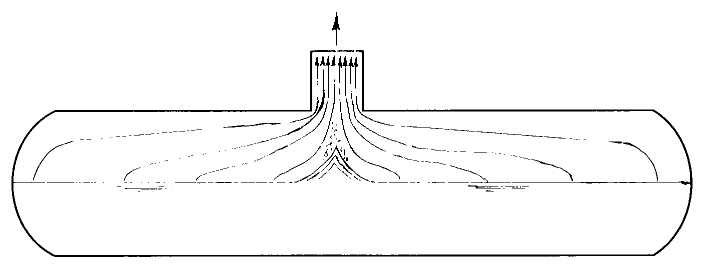
[0044] The steam generation equipment that the present embodiment relates to produces saturated steam, such as figure 2 with 3 As shown, its output steam volume D=10t / h, steam pressure P=1.6MPa.g,

[0045] The cross-section of the steam equalizing pipe is circular, the length L=20m, and the inner diameter is 0.08m. The number of segments of the equalizing pipe is n=12, the opening diameter of the equalizing pipe is d=0.0075m, and the total number of openings is 274.

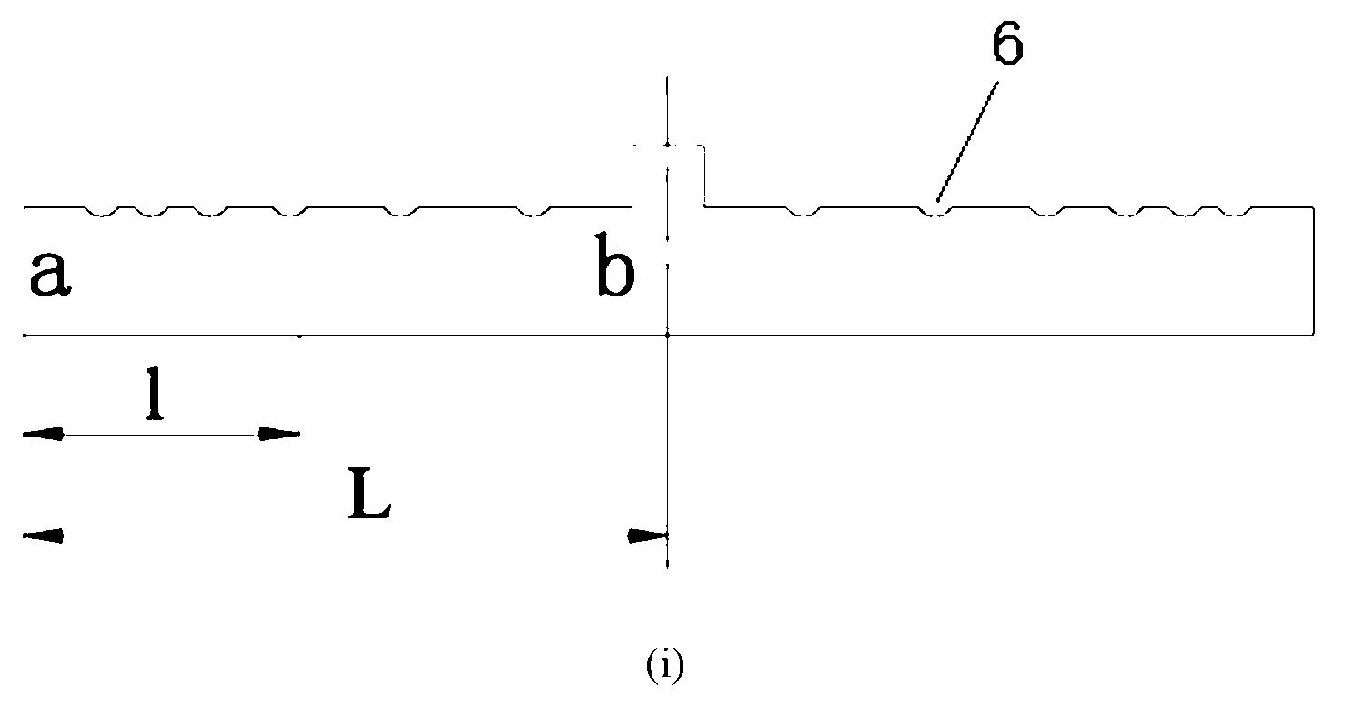
[0046] The horizontal part of the steam equalizing pipe is 0.10mm away from the upper edge of the inner wall of the drum, image 3 The opening of each segment is represented by a hole, the aperture d of the opening is the same, and the spacing S of the opening decreases gradually from both ends to the center line along the length of the flow equalizing tube.

[0047] From the end of the equalizing pipe to the middle, the pressure difference ΔP between the pressure of the steam in the drum and the steam pressur...

Embodiment 2

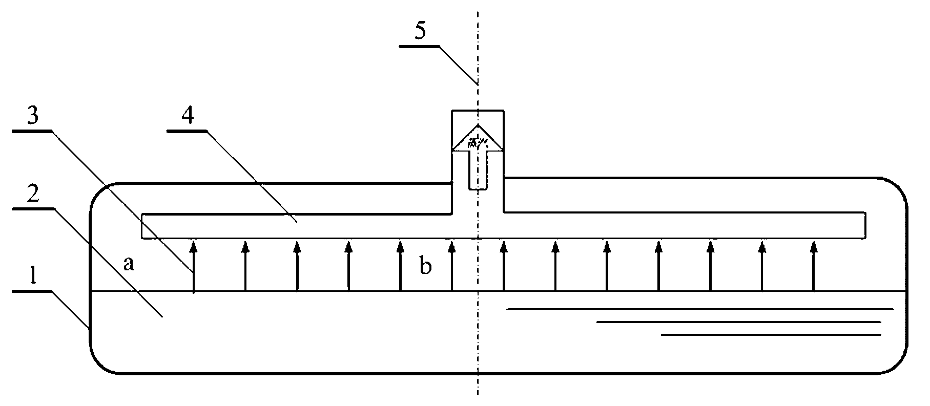
[0052] The steam generation equipment that the present embodiment relates to produces saturated steam, such as figure 2 with 4 As shown, its output steam volume D=10t / h, steam pressure P=1.6MPa.g,

[0053] The cross-section of the steam equalizing pipe is circular, the length L=20m, and the inner diameter is 0.08m. The number of segments of the equalizing pipe is n=12, and the total number of openings is 276.

[0054] The horizontal part of the steam equalizing pipe is 0.1m away from the upper edge of the inner wall of the drum, Figure 4 The opening of each section is represented by one hole, the number of openings in each section of flow equalizing pipe is 23, and the pitch S is 0.072m. Along the length of the flow equalizing tube, the diameter of the opening from both ends to the centerline gradually decreases.

[0055] From the end of the equalizing pipe to the middle, the pressure difference ΔP between the pressure of the steam in the drum and the steam pressure in th...

Embodiment 3

[0060] For the combustion equipment involved in this embodiment, the total flow of flue gas is V=168162nm 3 / h. The flue gas is drawn out with 7 flues. The length of each flue is 23.62m, the width is 0.58m, and the height is 2.33m. There are 9 rectangular openings along the length of each flue to introduce flue gas from the combustion chamber.

[0061] According to the calculation result of formula (5), the static pressure of the flue gas along the length of the flue is in the range of -0.7 to -125Pa. Along the length of the flue, the static pressure of the flue gas gradually decreases from the end to the outlet opening.

[0062] The area of ​​the 9 openings along the length of the flue is shown in the table below:

[0063]

[0064] At the end of the flue, due to the small pressure difference between the pressure of the flue gas in the combustion chamber and the pressure of the flue gas in the flue, the area of ​​the opening is larger, and at the outlet of the flue due t...


PUM


Abstract

The invention relates to a method and a device for implementing uniform flow of steam in a boiler barrel. An inverted T-shaped steam flow equalizing pipe bundle is arranged at the upper part inside the boiler barrel and a plurality of openings are non-uniformly distributed on steam flow equalizing pipes (horizontal parts), so that the steam uniformly flows upwards to enter the flow equalizing pipes and then is led out of the boiler barrel; opening apertures or opening densities along the lengths of the flow equalizing pipes are calculated and determined according to static pressure distribution design of the steam in the flow equalizing pipes in the flowing process and the steam from a steam space of the boiler barrel to the flow equalizing pipes uniformly flows upwards, so that the disadvantage that water is carried in the steam is avoided. The invention aims to avoid the phenomenon that the water surface of saturated water in a middle region of the boiler barrel is upsurged, and fundamentally eliminate the problem that water is carried in the output steam, so that operation reliability of steam generation equipment is improved.

Description

technical field [0001] The present invention relates to a method and device in the technical field of steam generating equipment or combustion equipment, in particular to a method and device for realizing uniform flow of steam or flue gas in a drum. Background technique [0002] In the drums of steam generating equipment such as industrial boilers, waste heat boilers, and heat accumulators, there are two fluids, saturated water and saturated steam (saturated water is in the lower part, and saturated steam is in the upper part). When the length of the drum is relatively large, and there is only one pipe in the upper part of the drum to draw saturated steam from the drum, even if a steam-water separator is installed at the steam outlet, water in the steam cannot be avoided. Because the flow velocity gradually increases in the process of steam flowing from both sides of the drum to the middle in the steam space, the steam longitudinal flow velocity is the highest near the middl...

Claims


Application Information

Patent Timeline
Patent Type & Authority Applications(China)
IPC IPC(8): F22B37/22F23J11/00
Inventor 王孟浩王衡
Owner SHANGHAI WANGTE ENERGY RESOURCE SICENCE & TECH
Why Eureka
Try Eureka