Method and equipment for detecting coverage of reference mark channel

A technology of reference symbols and detection methods, which is applied in the field of coverage detection of reference symbol channels, can solve problems such as difficult detection and inappropriate parameter settings, and achieve the effects of reducing maintenance costs, reducing workload, and improving accuracy

Inactive Publication Date: 2010-12-22
CHINA ACAD OF TELECOMM TECH
View PDF2 Cites 20 Cited by
  • Summary
  • Abstract
  • Description
  • Claims
  • Application Information

AI Technical Summary

Problems solved by technology

[0011] The deficiency of prior art is: although existing method is indeed a simple method, its accuracy is closely related to the distribution of users, if the users are approximately evenly distributed in the cell, it will be more accurate; however, if most users If they are all concentrated in the center of the cell, or only a few users are distributed on the edge of the cell, it is difficult to detect; in addition, the above problems are judged to be coverage problems, but in fact the problem may also be that the parameters related to A1, A2 or A3 are not properly set

Method used


Image

  • Method and equipment for detecting coverage of reference mark channel
  • Method and equipment for detecting coverage of reference mark channel
  • Method and equipment for detecting coverage of reference mark channel

Examples


Embodiment 1

[0084] This embodiment mainly introduces an implementation manner of reusing the A2 event to detect weak coverage of the RS channel.

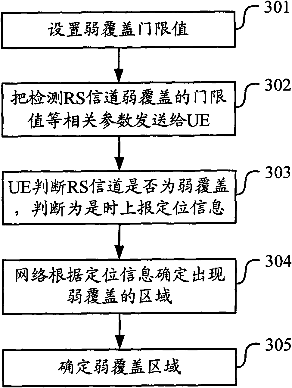
[0085] image 3 It is a schematic diagram of the implementation process of the weak coverage detection method of the RS channel in Embodiment 1. As shown in the figure, the following steps may be included when performing weak coverage detection:

[0086] Step 301, setting a weak coverage threshold.

[0087] In implementation, according to engineering experience or simulation results, set a weak coverage threshold for the RS channel, which is recorded as Thresh-Weak; different Thresh-Weak can be configured for different scenarios, such as dense urban areas, general urban areas, suburbs, or sea , you can also set different Thresh-Weak according to the UE's moving speed.

[0088] The threshold value of reusing the A2 event is a weak coverage threshold value to avoid modification of the existing specification. Therefore, this embodiment will use ...

Embodiment 2

[0099] Embodiment 1 describes the reuse of existing A2 events. During implementation, this embodiment can also be used alone, or this embodiment can be used simultaneously on the basis of Embodiment 1. This embodiment mainly adds an A2 event, and Give the event a new ID, namely:

[0100] Added different A2 event measurements;

[0101] Set the increased A2 event threshold with different identifications as the weak coverage threshold;

[0102] The UE performs additional A2 event measurements with different identities;

[0103] The UE takes the added A2 event measurement results with different identities as the measurement results.

[0104] In the way of starting a new A2 event for weak coverage detection, it can be as follows when performing weak coverage detection:

[0105] According to engineering experience or simulation results, set a weak coverage threshold for the RS channel, which is denoted as Thresh-Weak; different Thresh-Weak can be configured for different scenario...

Embodiment 3

[0110] This embodiment mainly introduces an implementation manner of detecting weak coverage of the RS channel by using the minimized drive test. which is:

[0111] In the minimization drive test, it is set to detect the weak and / or over-coverage of the RS channel.

[0112] Feedback positioning information to the network side is set in the minimization drive test.

[0113] Apparently, the scheme adopted in this embodiment can be used alone, or can be adopted simultaneously with Embodiments 1 and 2, and there is no contradiction among the three.

[0114] Figure 4 It is a schematic diagram of the implementation process of the weak coverage detection method of the RS channel in Embodiment 3. As shown in the figure, Embodiment 3 is an embodiment of UE log (recording) the signal strength of the cell signal lower than a certain threshold and its auxiliary information, specifically in The following steps may be included when performing weak coverage detection:

[0115] Step 401:...


PUM


Abstract

The invention discloses a method and equipment for detecting the coverage of a reference mark channel. The method comprises: setting over-coverage thresholds of a service cell and neighboring cells; when detecting the over-coverage of the reference mark channel, allowing user equipment to acquire a measurement result which comprises a lagged value of the service cell and a reference signal receiving power value or comprises the lagged value of the service cell and the reference signal receiving quality value; and allowing the user equipment to send a measurement report to a network according to the measurement result and the over-coverage thresholds of the service cell and the neighboring cells. When the method and the equipment are used, the accuracy of fault detection can be improved.

Description

technical field [0001] The invention relates to wireless communication technology, in particular to a coverage detection method and equipment of a reference symbol channel. Background technique [0002] In the network optimization work of mobile communication system, coverage planning and optimization is one of the most important tasks. Traditional network planning is done manually, which undoubtedly consumes a lot of manpower and material resources. After the network evolves to the LTE (Long Term Evolution, long-term evolution) stage, people hope that this part of the work can be automatically completed as much as possible. Therefore, in the self-optimization issue of SON (Self Organizing Networks, self-organizing network) of 3GPP (3rd Generation partnership project, 3rd generation cooperation project), the use case of CCO (Coverage and Capacity Optimization, coverage and capacity optimization) was introduced. At the 3GPP RAN3 Korean meeting in March 2009, it was clarifie...

Claims


Application Information

Patent Timeline
Patent Type & Authority Applications(China)
IPC IPC(8): H04W16/18H04W24/10H04W88/02
Inventor 赵瑾波秦飞董书霞
Owner CHINA ACAD OF TELECOMM TECH
Why Eureka
Try Eureka