Retraction structure for safety syringe

A technology for safe syringes and needle seats, applied in the field of retraction devices, can solve problems such as drug and blood contamination, lower yield, needle seat shrinkage or leakage

Inactive Publication Date: 2010-12-29
张淑茗
View PDF0 Cites 11 Cited by
  • Summary
  • Abstract
  • Description
  • Claims
  • Application Information

AI Technical Summary

Problems solved by technology

[0002] Most of the syringes currently on the market are traditional, including injection needles without any safety devices. Not only can they be reused, but they are likely to cause drug and blood contamination. In addition, the exposed injection needles have caused medical staff and Stabbings by cleaning staff, deepening epidemic
Therefore, in view of the above-mentioned problems existing in the structure of conventional syringes, how to develop a syringe that can avoid secondary pollution caused by repeated use is the ardent expectation of consumers, and it is also the goal that relevant companies must work hard to develop and break through. direction
[0003] At present, the needle seat of the retractable safety injection needle is designed to be fixed on the opening end of the barrel by a frictional resistance method. Such a fixed design is easy to cause the needle seat of the injection needle to be damaged due to thermal expansion and contraction of the external temperature. The outer edge and the tightly positioned barrel produce unexpected phenomena, such as the sharp rise in temperature that reduces the fit between the needle seat and the barrel, causing the needle seat to shrink or leak during the injection process, or Due to the sudden drop in temperature, excessive engagement, the injection needle and the needle seat cannot be retracted into the barrel after the injection, resulting in serious failure of injection needle quality control and lower yield rate. It is necessary to actively seek solutions.

Method used


Image

  • Retraction structure for safety syringe
  • Retraction structure for safety syringe
  • Retraction structure for safety syringe

Examples


Embodiment Construction

[0025] Now illustrate the present invention in conjunction with accompanying drawing and embodiment.

[0026] The main component symbols are explained as follows:

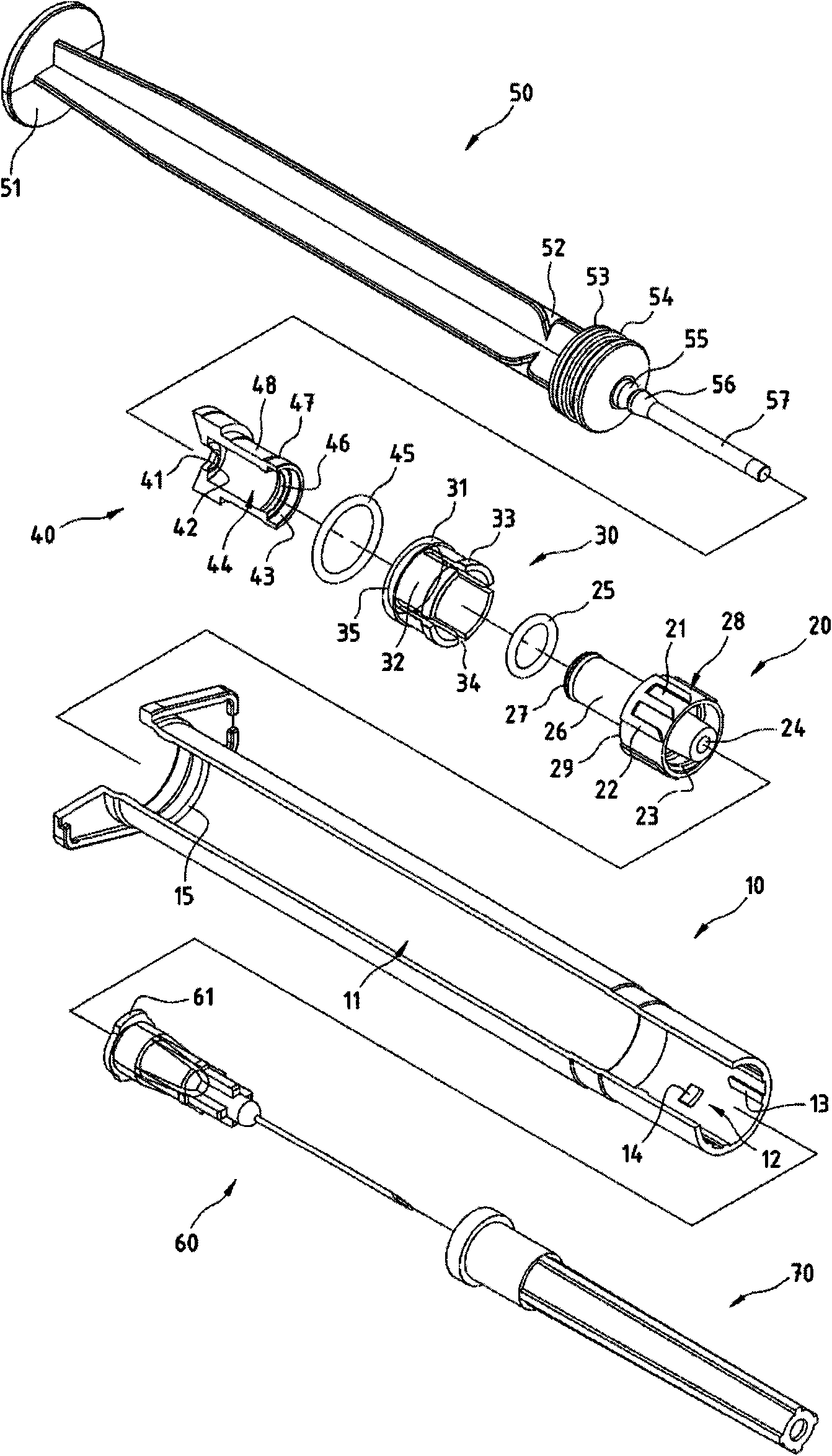
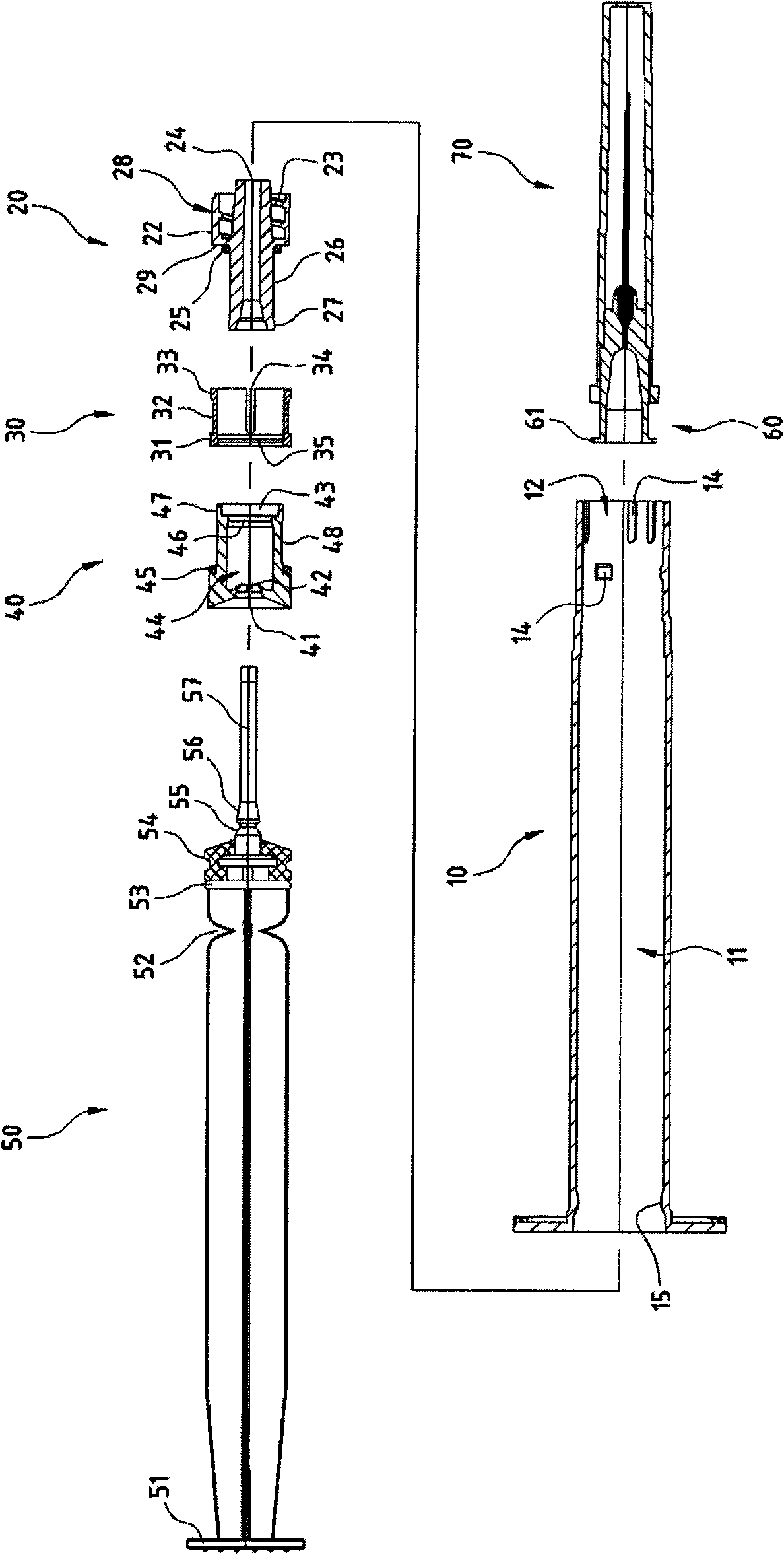
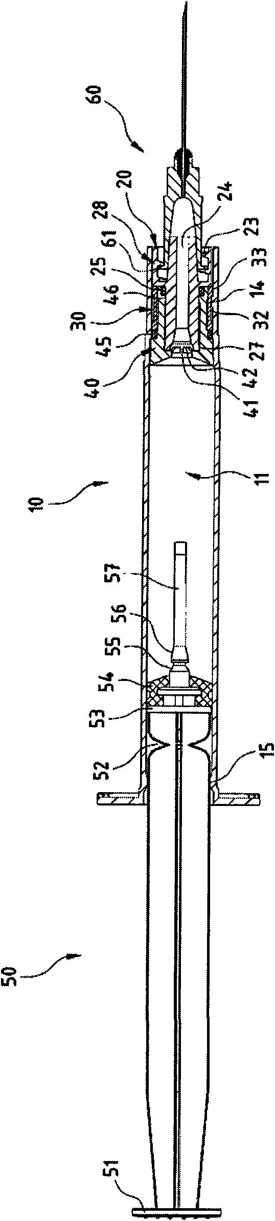
[0027] Cylinder body (10), chamber (11), open end (12), rotation limiting piece (13), stopper (14), stopper edge (15), first needle seat (20), rear stopper (21 ), limited rotation seat (22), solid lock groove (23), threaded part (24), O-ring (25), guide rod (26), flange (27), accommodating part (281), front end seat (28), retaining wall (29), fitting space (261), second needle seat (30), seat end (31), shrapnel body (32), embedding part (33), compression space (34), Fitting edge (35), third needle seat (40), fastening part (41), retaining end (42), fitting space (43), guide groove (44), O-ring (45), fitting joint (46), embedded flange (47), front column end (48), push rod (50), thrust end (51), break (52), stop end (53), rubber plug (54 ), stopper (55), buckle end (56), push rod head (57), injection needle (60),...


PUM


Abstract

The invention provides a retraction device for a safety syringe, in particular a creative design that a syringe needle bed is stably positioned at an opening end of a barrel. A borrow locking device and a retraction embedded linkage device are arranged between needle beds mutually. Due to the creative and unique design, a pull rod head of a pull rod can be rapidly clamped to be positioned on a needle bed group by means of the borrow locking device and the retraction embedded linkage device so as to provide convenience for a user to perform the next retraction action. Meanwhile, the needle bed group can be stably assembled and positioned at the opening end of the barrel and hardly makes clamping and sealing functionally damaged due to external temperature change. For example, the clamping degree between the needle bed and the barrel is reduced due to steep temperature rise so as to cause the inner retraction or leakage of the needle bed in the injection process, or the needle bed and the barrel are excessively clamped due to steep temperature reduction, and the injection needle cannot retract after injection and the needle bed enters the barrel, and the like. Therefore, the retraction device for the safety syringe can improve the safety and environmental protection quality.

Description

technical field [0001] The invention relates to a retracting device of a safety syringe. Background technique [0002] Most of the syringes currently on the market are traditional, including injection needles without any safety devices. Not only can they be reused, but they are likely to cause drug and blood contamination. In addition, the exposed injection needles have caused medical staff and The stabbing of cleaning staff deepens the epidemic of infectious diseases. Therefore, in view of the above-mentioned problems existing in the structure of conventional syringes, how to develop a syringe that can avoid secondary pollution caused by repeated use is the ardent expectation of consumers, and it is also the goal that relevant companies must work hard to develop and break through. direction. [0003] At present, the needle seat of the retractable safety injection needle is designed to be fixed on the opening end of the barrel by a frictional resistance method. Such a fixe...

Claims


Application Information

Patent Timeline
Patent Type & Authority Applications(China)
IPC IPC(8): A61M5/50A61M5/31
CPCA61M5/322A61M5/3202A61M5/3234A61M5/5066A61M5/34
Inventor 张淑茗
Owner 张淑茗
Why Eureka
Try Eureka