High-precision friction dynamic process testing device and method

A testing device and dynamic process technology, which is applied in the direction of measuring device, measuring force, power measurement, etc., can solve the problems of low friction test accuracy, difficulty in testing static and dynamic friction of the measured object, and inability to test friction, etc., to achieve simple structure , friction testing is accurate, and the operation is convenient

Inactive Publication Date: 2010-12-29
NORTHWESTERN POLYTECHNICAL UNIV
View PDF2 Cites 13 Cited by
  • Summary
  • Abstract
  • Description
  • Claims
  • Application Information

AI Technical Summary

Problems solved by technology

[0005] In order to overcome the shortcomings in the prior art that it is impossible to test the static change process of friction force, it is difficult to test the static and dynamic friction force

Method used


Image

  • High-precision friction dynamic process testing device and method
  • High-precision friction dynamic process testing device and method
  • High-precision friction dynamic process testing device and method

Examples


Embodiment 1

[0041] This embodiment is a device for testing the dynamic process of the friction force of the lead screw pair, including a bench, power components, tooling components of the tested piece and a control system.

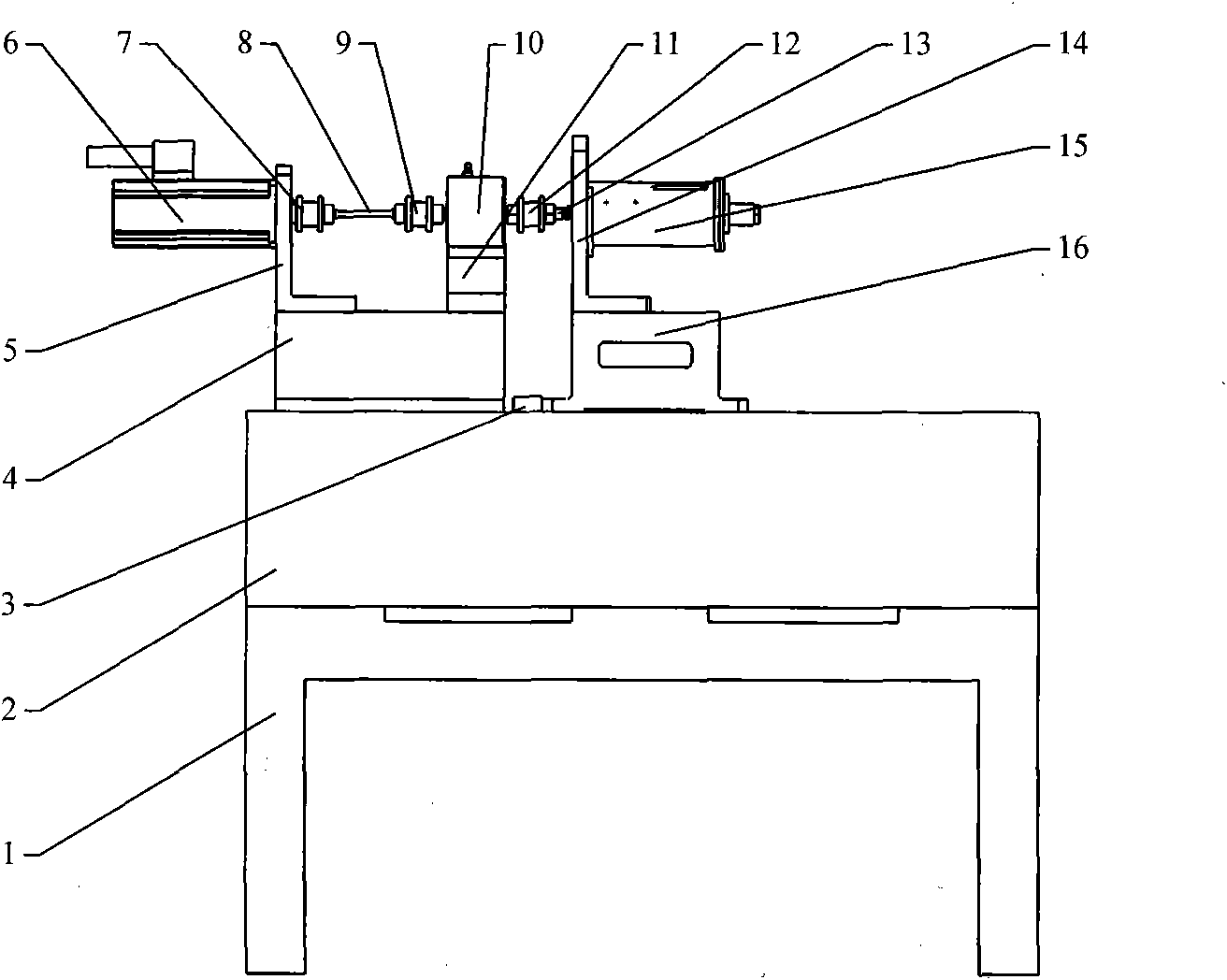
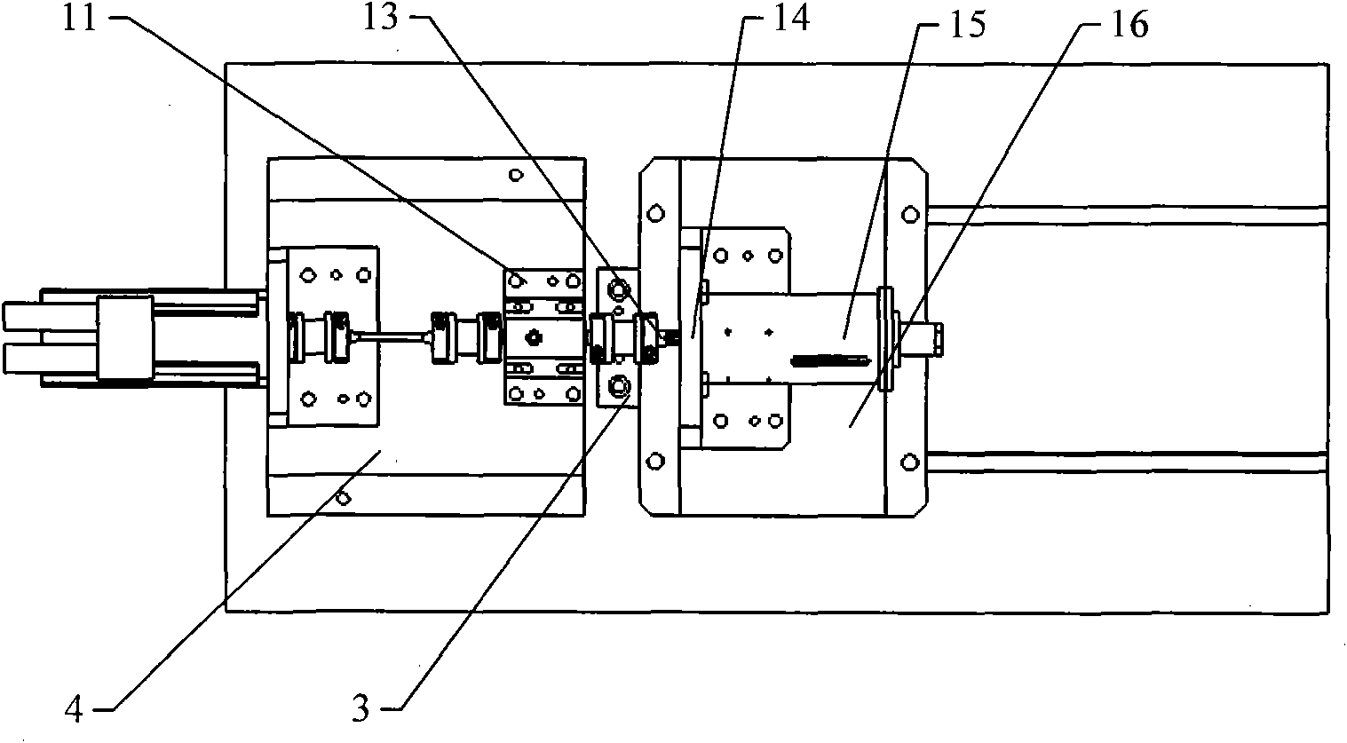
[0042] Such as figure 1 , figure 2 As shown, the stand includes a bracket 1 , a table top 2 and a positioning bar 3 , and the bracket 1 is fixed to the ground, and the table top 2 is fixed on the bracket 1 . The strip-shaped positioning bar 3 whose end face is rectangular is fixed on the middle part of the upper surface of the table top 2 along the width direction of the table top 2; a pair of T-shaped slots are arranged on the upper surface of the table top 2, and the T-shaped slots are located on one side of the positioning bar 3 and are aligned with the positioning bar. Bar 3 is vertical.

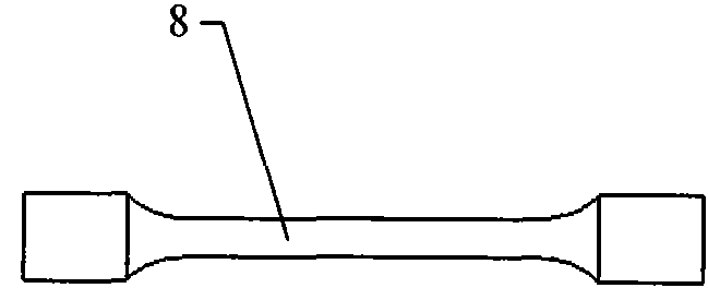
[0043]The power component includes a power component support 4, a servo motor 6 and a motor support base 5, a motor coupling 7, a torsion bar spring 8, a sensor coupling 9, ...

Embodiment 2

[0058] This embodiment is a device for testing the dynamic process of friction force of a gear pair, including a bench, a power component, a tooling component of a test piece and a control system.

[0059] Such as Figure 5 , Image 6 As shown, the stand includes a bracket 1 , a table top 2 and a positioning bar 3 , and the bracket 1 is fixed to the ground, and the table top 2 is fixed on the bracket 1 . The strip-shaped positioning bar 3 whose end face is rectangular is fixed on the middle part of the upper surface of the table top 2 along the width direction of the table top 2; a pair of T-shaped slots are arranged on the upper surface of the table top 2, and the T-shaped slots are located on one side of the positioning bar 3 and are aligned with the positioning bar. Bar 3 is vertical.

[0060] The power component includes a power component support 4, a servo motor 6 and a motor support base 5, a motor coupling 7, a torsion bar spring 8, a sensor coupling 9, a torque senso...


PUM

PropertyMeasurementUnit
Leadaaaaaaaaaa
Pitchaaaaaaaaaa

Abstract

The invention relates to a high-precision friction dynamic process testing device and a high-precision friction dynamic process testing method. A motor coupler (7) is connected with a servo motor (6); two ends of a torsion bar spring (8) are connected with the motor coupler (7) and a sensor coupler (9) respectively; an input end and an output end of a torque sensor are connected with the coupler (9) and a coupler (12) respectively; two ends of the coupler (13) are connected with a tested piece (15) and a spline shaft coupler (12) respectively; and when the torque elastic deformation and the torque of the torsion bar spring (8) are in a linear relationship, the precision is 0.1 percent. Due to the adoption of a periodic testing method, because the torsion bar spring is arranged to partially absorb the vibration and displacement of the servo motor, the dynamic testing precision on the friction force is 0.3 percent. The high-precision friction dynamic process testing device has the advantages of simple structure, convenient operation, and measurement of the dynamic change process of static and dynamic friction at any point of various rotatably input or output mechanisms.

Description

1. Technical field [0001] The invention relates to the field of friction test of mechanical design, in particular to a high-precision friction dynamic process test device and a test method. 2. Background technology [0002] A shafting friction torque tester is disclosed in the patent application document with the patent number 200720089567.6. Such as Figure 9 As shown, the tester includes a servo motor 6, a synchronous toothed belt 21, a photoelectric encoder 22, a supporting spindle 23, a table 2, a chuck 24, a column guide rail 26, a torque sensor 10 and a shaft system 25 to be tested. The instrument can test the friction torque of the shaft system, but the friction torque of the measured object is very small, and the static change process of the friction torque cannot be measured; at the same time, the test object of the instrument has certain limitations, and can only be tested for the shaft system . [0003] A utility model patent with the patent number of 02226928.2...

Claims


Application Information

Patent Timeline
IPC IPC(8): G01L1/00G01L3/00
Inventor 秦现生谭小群张双权陈耀东蒋明桔沈宏华
Owner NORTHWESTERN POLYTECHNICAL UNIV
Why Eureka
Try Eureka