
Focus control circuit

A focus control and circuit technology, which is applied in the direction of focus devices, focus devices, camera focus devices, etc., can solve problems such as time-consuming, and achieve the effect of improving focus accuracy

Active Publication Date: 2010-12-29
SANYO ELECTRIC CO LTD +1
View PDF7 Cites 19 Cited by
  • Summary
  • Abstract
  • Description
  • Claims
  • Application Information

AI Technical Summary

Problems solved by technology

However, there is a problem that it takes time to detect the lens position where the contrast of the subject is maximized

Method used


Image

  • Focus control circuit
  • Focus control circuit
  • Focus control circuit

Examples


Embodiment Construction

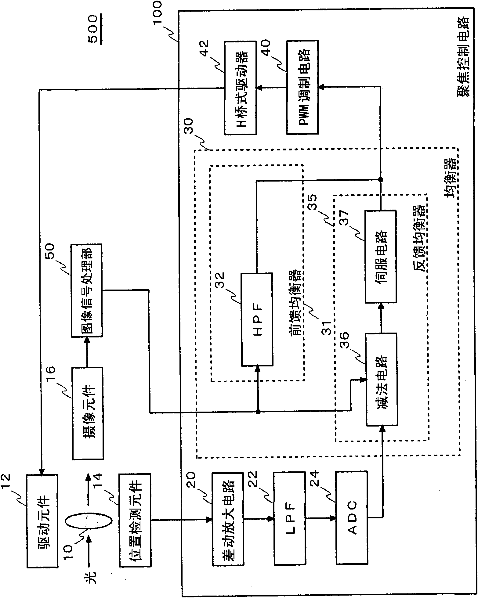
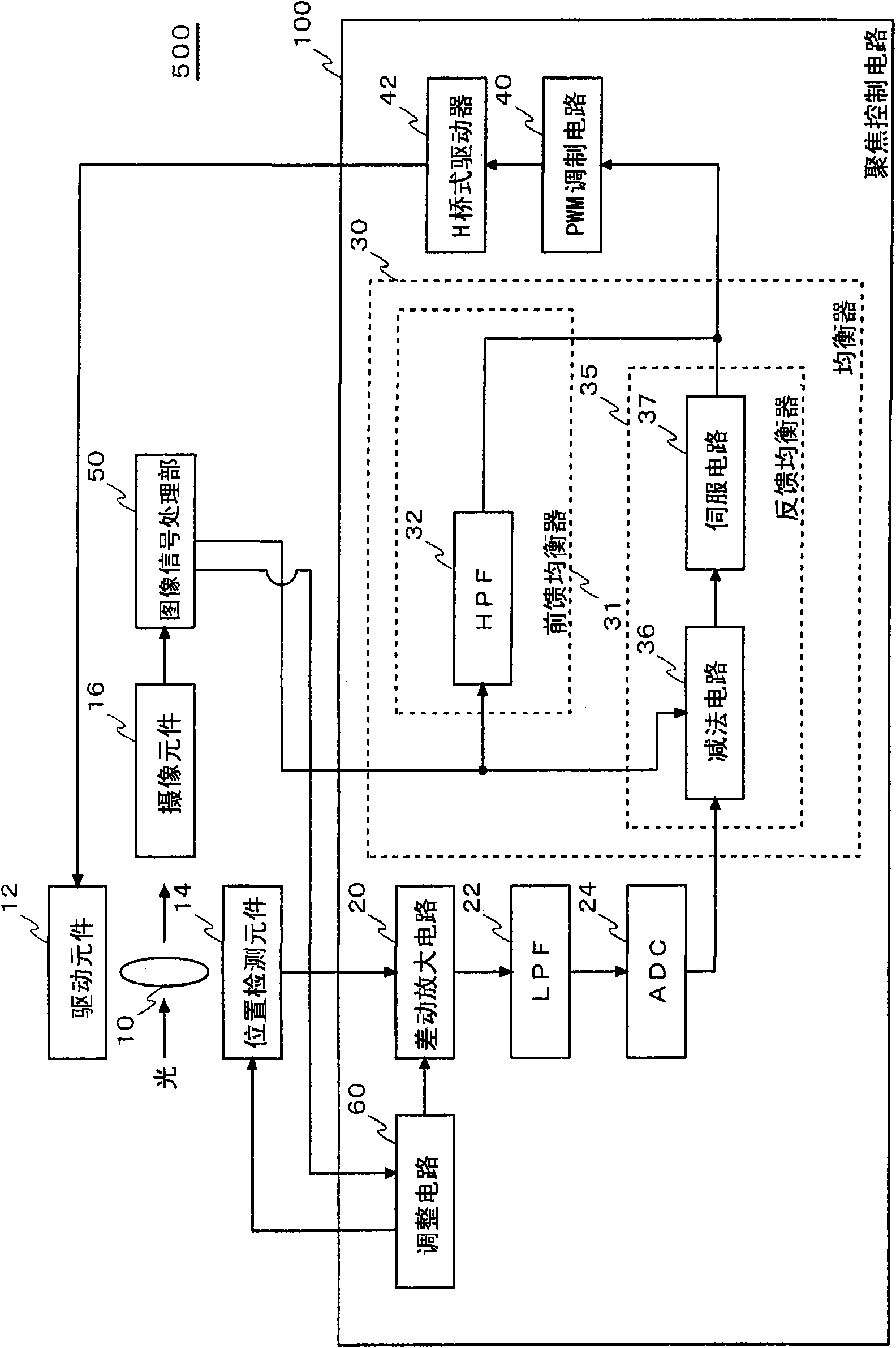
[0016] figure 1 It is a diagram showing the configuration of the imaging device 500 equipped with the focus control circuit 100 according to the first embodiment. The imaging device 500 includes a lens 10 , a drive element 12 , a position detection element 14 , an imaging element 16 , an image signal processor (ISP: Image Signal Processor) 50 , and a focus control circuit 100 . Here, constituent elements not related to autofocus control, such as an image encoding engine and a recording medium, are omitted.

[0017] The imaging element 16 converts an optical signal transmitted through the lens 10 as an optical component into an electrical signal, and outputs it to the image signal processing unit 50 . The imaging element 16 may use a CCD sensor or a CMOS image sensor.

[0018] The drive element 12 is an element for adjusting the position of the lens 10 , and moves the lens 10 in the direction of the optical axis based on a drive signal supplied from the focus control circuit ...


PUM


Abstract

The invention provides a focus control circuit (100) installed in an image pickup apparatus (500) including a lens (10), a driver element (12) for adjusting the position of the lens (10), and a position detecting element (14) for detecting the position of the lens (10). A feedback equalizer (35) included in the focus control circuit (100) generates a drive signal used to adjust the position of the lens (10) to a target position, based on a difference between the position of the lens (10) identified by the output signal of the position detecting element (14) and the target position of the lens (10) set externally, and controls the driver element (12).

Description

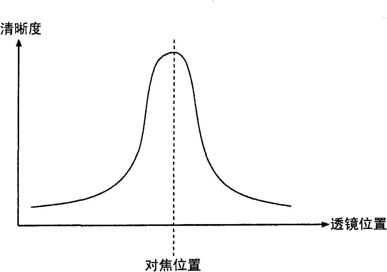
technical field [0001] The present invention relates to a focus control circuit that actually moves a lens to determine a focus position. Background technique [0002] Many camera modules mounted in general digital cameras and mobile phones are equipped with an auto-focus function. In the autofocus function mounted on such a compact camera, a contrast detection method is often used. The contrast detection method is a method of actually moving a lens to detect a lens position at which the contrast of a subject in a captured image is maximized, and moves the lens to this position (for example, refer to Patent Document 1). [0003] [Patent Document 1]: JP-A-2006-166403 [0004] Compared with the active method of irradiating infrared rays or ultrasonic waves to a subject and measuring the distance to the subject from the reflected waves, the contrast detection method can be realized at a lower cost. However, there is a problem that it takes time to detect the lens position at...

Claims


Application Information

Patent Timeline
Patent Type & Authority Applications(China)
IPC IPC(8): G03B13/36G02B7/28H04N5/225G03B30/00
CPCG03B3/10H04N5/23212G02B7/38H04N23/675G02B7/09G03B13/36G03B2205/0053
Inventor 津田广之藏武
Owner SANYO ELECTRIC CO LTD
Learn More