Radio frequency identification (rfid) device and method for testing the same

A radio frequency identification and equipment technology, applied in radio frequency circuit testing, electronic circuit testing, instruments, etc., can solve problems such as incompatibility with cost-effectiveness and inefficiency

Inactive Publication Date: 2010-12-29
SK HYNIX INC
View PDF1 Cites 5 Cited by
  • Summary
  • Abstract
  • Description
  • Claims
  • Application Information

AI Technical Summary

Problems solved by technology

[0015] However, there are more than thousands of RFID tags in one wafer, making the above test method of applying an RF signal to each of all RFID tags not cost-effective and inefficient

Method used


Image

  • Radio frequency identification (rfid) device and method for testing the same
  • Radio frequency identification (rfid) device and method for testing the same
  • Radio frequency identification (rfid) device and method for testing the same

Examples


Embodiment Construction

[0088] Reference will now be made in detail to embodiments of the invention, examples of which are illustrated in the accompanying drawings. Wherever possible, the same reference numbers will be used throughout the drawings to refer to the same or like parts.

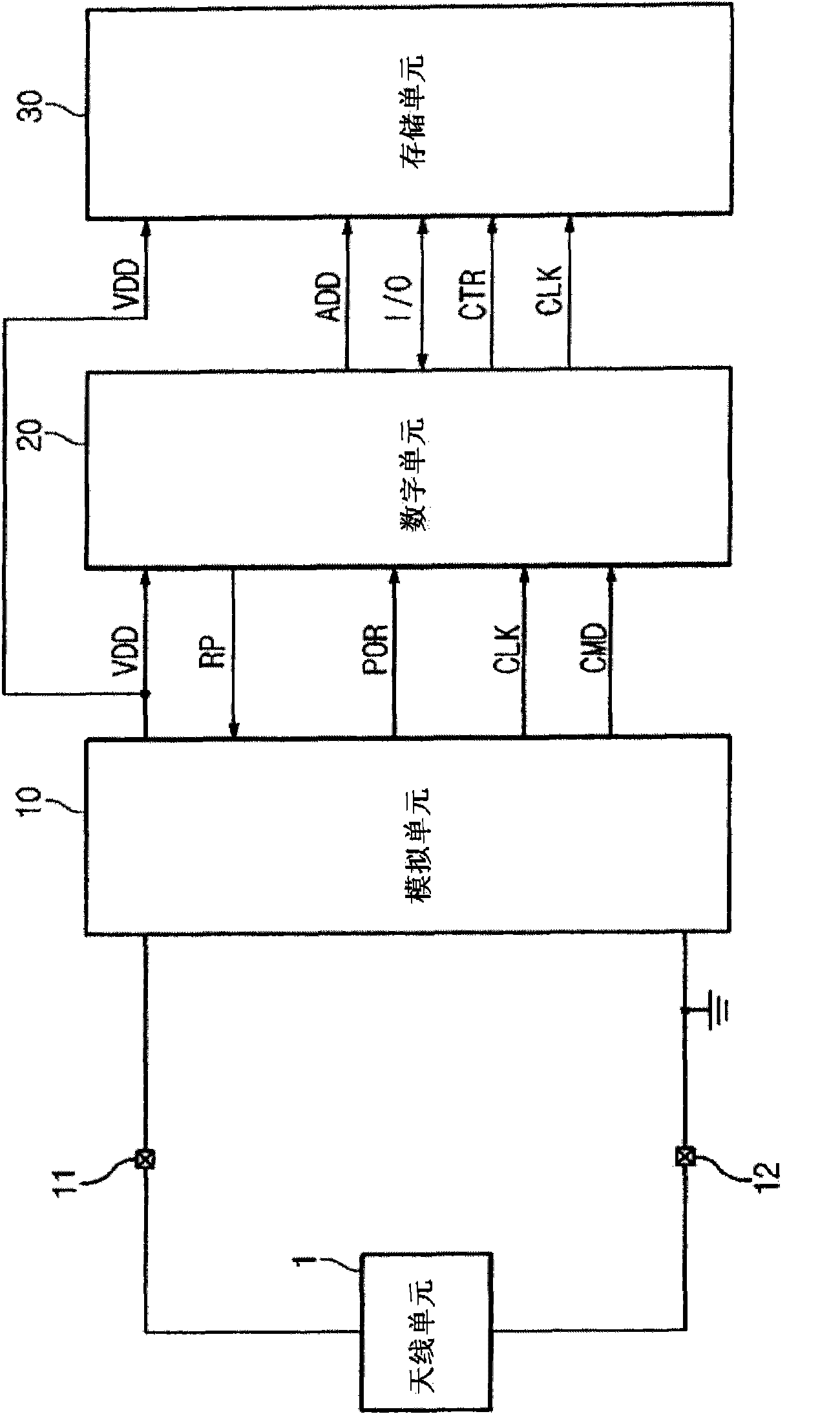
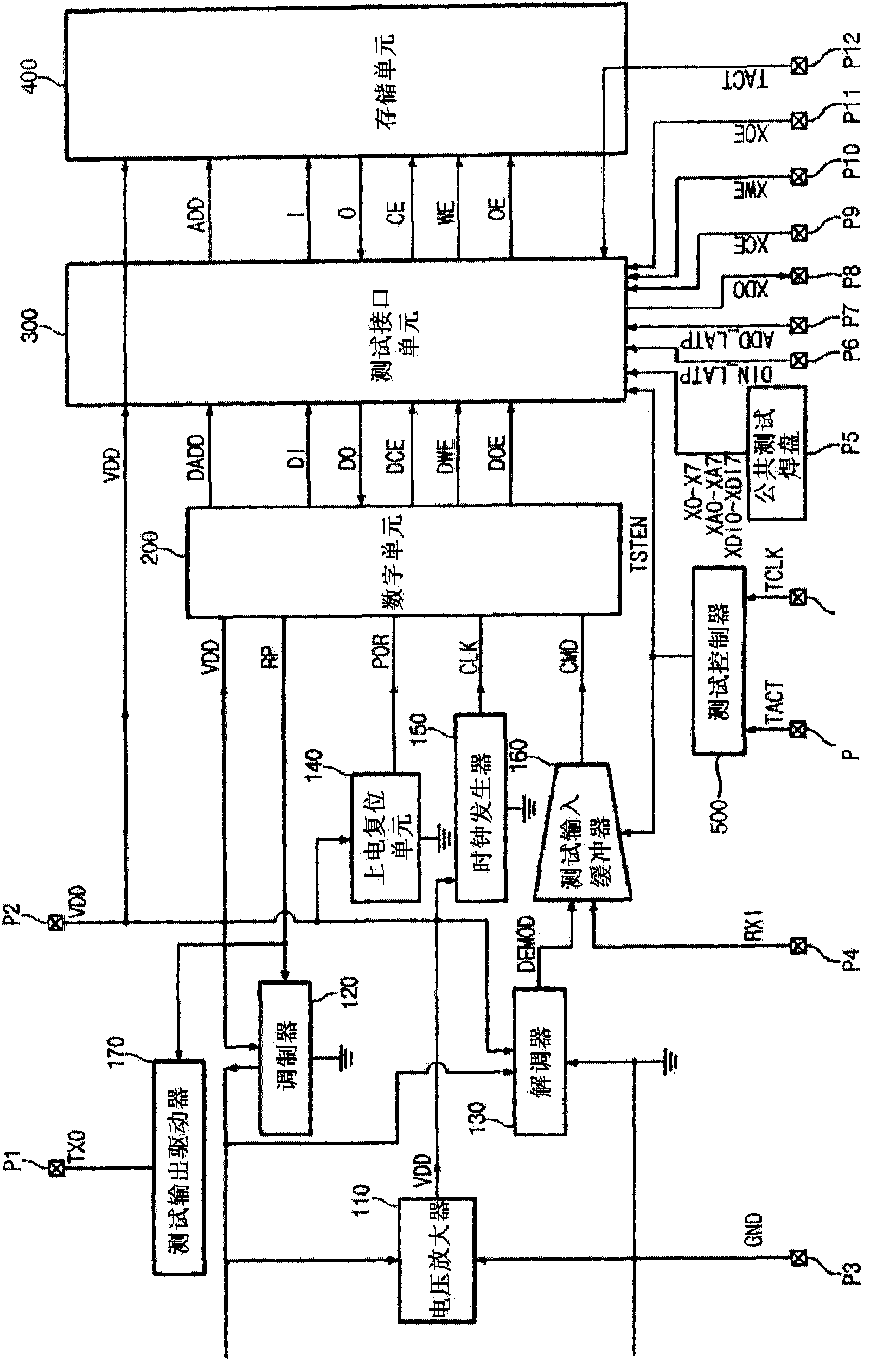
[0089] figure 2 is a structural diagram illustrating a radio frequency identification (RFID) tag chip used in an RFID device according to an embodiment of the present invention. In an embodiment of the invention, a plurality of pads P1, P2...P13 are provided in the test chip.

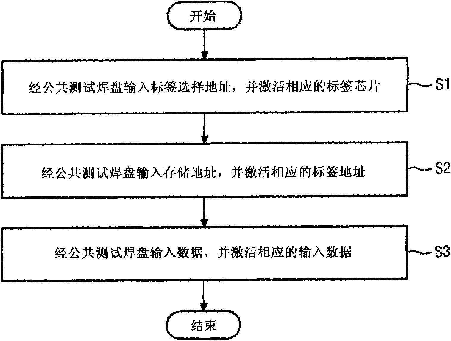
[0090] In an embodiment of the present invention, while the chip is still on the wafer, the measurement signal is sent via the common test pad (i.e., no radio frequency (RF) signal needs to be received via the antenna), so that the performance or throughput of the RFID tag can be easily tested quantity.

[0091] The RFID device according to this embodiment of the present invention comprises a voltage amplifier 110, a modulator 120, a demodula...


PUM


Abstract

A radio frequency identification (RFID) device and a test method thereof are disclosed. In this test method, the RFID device receives different kinds of tag selection addresses and memory addresses according to a time sharing scheme, so that one or more RFID tags are tested. The RFID device includes a tag chip and a test chip. The tag chip performs a test operation upon receiving a test input signal from an external node, and externally outputs a test output signal indicating a result of the test operation. The test chip tests the tag chip upon receiving an address and data from an external node via a test pad during a test mode.

Description

[0001] Cross References to Related Applications [0002] This application claims priority from Korean Patent Application No. 10-2009-0056372, 10-2009-0056374, 10-2009-0056388, 10-2009-0056389 and 10-2009-0056390 filed on June 24, 2009, It is hereby incorporated by reference in its entirety. technical field [0003] Embodiments of the present invention relate to radio frequency identification devices and testing methods thereof, and more particularly to enabling one test chip to test multiple tags included in an array of tag chips at the wafer level (ie, before the wafer is diced into individual circuits). Chip testing techniques. Background technique [0004] Radio frequency identification (RFID) tag chips have been widely used to automatically identify objects by using radio frequency (RF) signals. In order to automatically identify an object using an RFID tag chip, an RFID tag is first attached to the object to be identified, and an RFID reader communicates wirelessly wi...

Claims


Application Information

Patent Timeline
Patent Type & Authority Applications(China)
IPC IPC(8): G06K7/00G01R31/28
CPCG06K7/0008G01R31/2822
Inventor 姜熙福洪锡敬
Owner SK HYNIX INC
Why Eureka
Try Eureka