Supercharge Your Innovation With Domain-Expert AI Agents!

Mould for molding magnetic core of soft ferrite

A soft ferrite and forming mold technology, applied in the manufacture of inductors/transformers/magnets, electrical components, circuits, etc., can solve the problems of high labor intensity of workers, waste of raw materials, affecting product performance, etc., to save labor costs, reduce The effect of scrap rate

Inactive Publication Date: 2010-12-29
ACME ELECTRONICS KUNSHAN
View PDF6 Cites 3 Cited by
  • Summary
  • Abstract
  • Description
  • Claims
  • Application Information

AI Technical Summary

Problems solved by technology

The processing and production process of this kind of air-gap magnetic core generally needs to go through green molding, sintering, grinding, and air-gap processing. Larger, the dimensional accuracy of the magnetic core air gap is difficult to control, which affects product performance, and the product yield is low. Inevitably there are problems such as waste of raw materials

Method used


Image

  • Mould for molding magnetic core of soft ferrite
  • Mould for molding magnetic core of soft ferrite

Examples


Embodiment

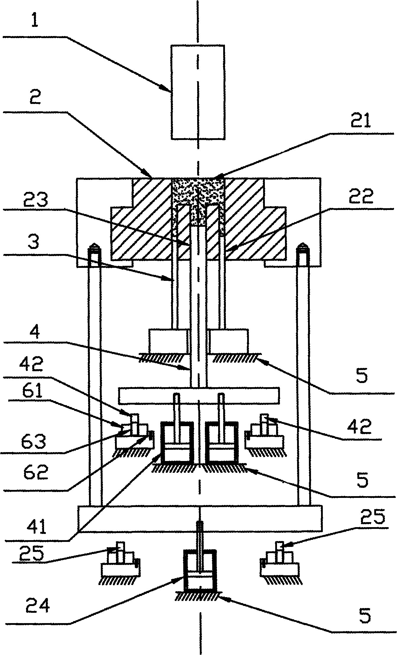
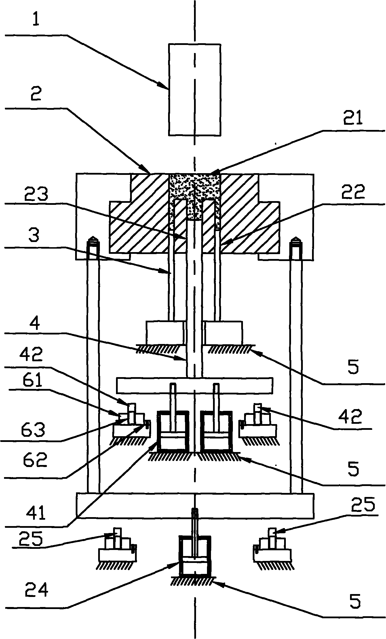
[0011] Embodiment: A mold for forming a soft ferrite core, including an upper punch 1, a middle die 2, a lower punch 3, a lower second punch 4, and a mold frame 5. Based on the direction of use, the middle die 2 can slide axially The set distance radial stop is positioned on the mold frame 5, the upper side of the middle mold 2 is provided with a forming groove 21, and the lower side of the middle mold 2 is respectively provided with the next punching hole 22 and the second punching hole 23. The upper end of the punching hole 22 and the lower two punching holes 23 communicate with the forming groove 21 of the middle mold 2, the lower end of the next punch 3 is fixed on the mold frame 5, and the upper end of the next punch 3 is axially slidable and inserted in the lower mold In the first punching hole 22, the lower end of the lower second punching 4 can slide axially at a set distance and the radial stopper is positioned on the mold base 5, and the upper end of the lower second ...


PUM


Abstract

The invention discloses a mould for molding the magnetic core of a soft ferrite, wherein a middle mould can axially slide a set distance and is radially positioned on a mould base in a fastening manner; the upper of the middle mould is provided with a molding groove, the downside thereof is respectively provided with a low punching hole 1 and a lower punching hole 2 the upper ends of which are communicated with the molding groove of the middle mould; the lower end of a lower punch 1 is fixedly arranged on the mould base, the upper end of the lower punch 1 is axially inserted in the lower punching hole 1 of the middle mould in a sliding mode, the lower end of a lower punch 2 can axially slide a set distance and is radially positioned on the mould base in a fastening manner, the upper end of the lower punch 2 is axially inserted in the lower punching hole 2 of the middle mould in a sliding manner, and the lower end of an upper punch is axially inserted in the molding groove on the upside of the middle mould. In the invention, the lower punch 1 and the lower punch 2 solely perform counter press on the upper punch to form the foot and the middle column of the product, namely respectively control the size and density of the foot and the middle column, an air gap of the middle column is preset, therefore only the thickness of the foot but not the middle column needs to be ground during subsequent grinding processes of products, thus reducing scrappage of the products and saving labor cost.

Description

technical field [0001] The invention relates to a metal forming die, in particular to a soft ferrite core forming die. Background technique [0002] In recent years, the trend of equipment components in the fields of computer, video and communication equipment is getting smaller and smaller. At the same time, the requirements for small volume and high precision of the magnetic core are getting higher and higher, especially for the accuracy of the air gap of the magnetic core. Higher, the traditional air-gap magnetic core processing method is to adjust the small air-gap grinding machine, and the operator performs air-gap grinding on the products one by one. Generally, air-gap magnetic cores are commonly used. The preparation process is mostly directly formed by a rotary molding machine. After high-temperature sintering and semi-finished size grinding, a small manual grinder is used to grind the air gap for the part that needs to be processed. The processing and production pr...

Claims


Application Information

Patent Timeline
IPC IPC(8): H01F41/02B22F3/03
Inventor 张健民熊勇王方灵
Owner ACME ELECTRONICS KUNSHAN
Features
  • R&D
  • Intellectual Property
  • Life Sciences
  • Materials
  • Tech Scout
  • Unparalleled Data Quality
  • Higher Quality Content
  • 60% Fewer Hallucinations
Learn More