

Series filter and low harmonic rectifier
A filter and rectifier technology, applied in harmonic reduction devices, AC networks to reduce harmonics/ripples, irreversible AC power input conversion to DC power output, etc., can solve the problems of increased complexity of rectifiers, power system hazards, Issues such as increased commutation gap
Inactive Publication Date: 2010-12-29
王家强
View PDF0 Cites 6 Cited by
- Summary
- Abstract
- Description
- Claims
- Application Information
AI Technical Summary
Problems solved by technology
Increasing the number of rectification phases doubles the complexity of the rectifier and increases the commutation gap, but the high-frequency harmonic components still exist, and the high-frequency harmonic components are very harmful to the power system.
Method used
View moreImage
Smart ImageViewing Examples

Examples
specific Embodiment approach
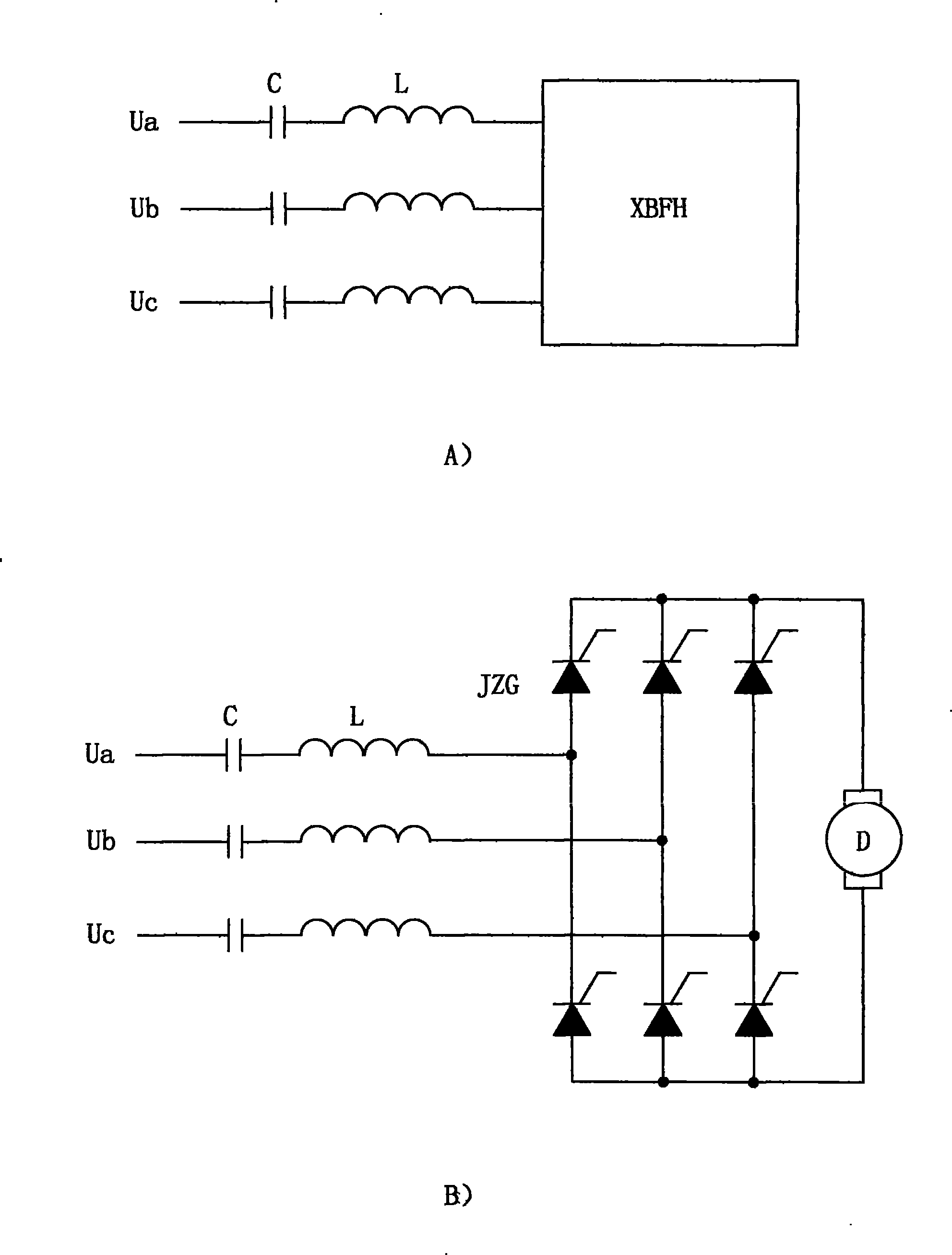
[0024] When the working voltage of XBFH is 380V, the maximum load current is 100A. The inductance of the inductor L is 6.4 millihenry, the capacitance of the capacitor C is 1600 microfarads, the working voltage of the inductor and the capacitor is 220V, and the working current is 100A.
[0025] A kind of embodiment of the low harmonic rectifier of the present invention is described below in conjunction with accompanying drawing B) part:
[0026] When the working voltage of the rectifier is 380V and the maximum load current is 100A. The inductance of the inductor L is 6.4 millihenry, the capacitance of the capacitor C is 1600 microfarads, the working voltage of the inductor and the capacitor is 220V, and the working current is 100A.
Login to View More PUM
 Abstract
The invention discloses a filter consisting of an inductor and a capacitor connected in series between a power supply and a load. The filter can filter harmonics with different frequencies. The power frequency fundamental wave impedance selection of the inductor or the capacitor is between 50 percent and 200 percent of load equivalent impedance (the load equivalent impedance is a ratio of a phase voltage effective value to a phase current effective value). A low harmonic rectifier formed by combining a series filter and a thyristor rectifier has low harmonic input current.
Description
Technical field: [0001] The invention relates to a filter device used for filtering out harmonics in a power system and a rectifying device capable of reducing harmonic currents. Background technique: [0002] Most of the existing harmonic filtering devices use passive parallel filters, and a set of filters is required for each harmonic frequency, and usually multiple sets of filters are required to filter out harmonics of different frequencies. The use of multiple sets of filters results in complex structure and high cost, and because the usual system contains harmonic components of infinite frequencies, it is impossible to filter out all the harmonics. [0003] Most of the existing rectifiers use the method of increasing the number of rectification phases to reduce the harmonic content, such as using 6-phase or 12-phase rectifiers. Increasing the number of rectification phases doubles the complexity of the rectifier and increases the commutation gap, but the high-frequenc...
Claims
Login to View More Application Information
Patent Timeline
 Patent Type & AuthorityApplications(China)
IPC IPC(8): H02J3/01H02M7/12
CPCY02E40/40
Inventor王家强
Owner王家强