Check patentability & draft patents in minutes with Patsnap Eureka AI!

Method for separating polarization multiplexing signals on the basis of optical interference effect

A polarization multiplexing and optical interference technology, which is applied in the field of polarization multiplexing signal separation based on optical interference effect, can solve problems such as differences in optical power and limited use occasions

Active Publication Date: 2010-12-29
WUHAN POST & TELECOMM RES INST CO LTD
View PDF4 Cites 2 Cited by
  • Summary
  • Abstract
  • Description
  • Claims
  • Application Information

AI Technical Summary

Problems solved by technology

The existing patent proposes to use the power difference method to demultiplex the polarization multiplexed signal at the receiving end. Since this method requires the polarization multiplexed two polarization channels to be optically decoherent, and the optical power of the two polarization channels must be different, it limits occasions of use

Method used


Image

  • Method for separating polarization multiplexing signals on the basis of optical interference effect
  • Method for separating polarization multiplexing signals on the basis of optical interference effect
  • Method for separating polarization multiplexing signals on the basis of optical interference effect

Examples


Embodiment Construction

[0031] The present invention will be described in further detail below in conjunction with the accompanying drawings.

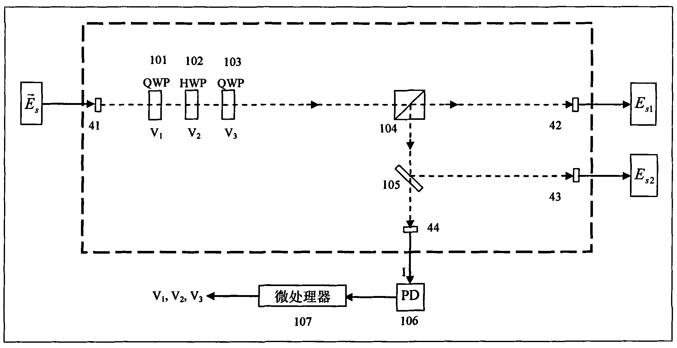
[0032] The polarization demultiplexer adopted in the present invention is as figure 1 As shown, the space light path is inside the dotted box.

[0033] The method for polarization multiplexing signal separation based on optical interference effect of the present invention comprises the following steps:

[0034] Step 1, the polarization multiplexed signal transmitted through the optical fiber link After being collimated by the first collimator 41, it is sent to the input end of the polarization demultiplexer as the polarization controller,

[0035] The polarization demultiplexer includes a first quarter wave plate (QWP) 101, a half wave plate (HWP) 102 and a second quarter wave plate (QWP) 103 connected in series in sequence,

[0036] The driving voltage V of the first quarter wave plate 101, the half wave plate 102 and the second quarter wave plate 103 1...


PUM


Abstract

The invention relates to a method for separating polarization multiplexing signals on the basis of optical interference effect. The method comprises the following steps of: regulating the polarization state of signal light in two polarization channels of a receiving end by using a polarization controller; controlling the polarization controller by detecting the change law of intensity of any path of output light of a polarizing beam splitter; selecting one path of output light of the polarizing beam splitter, splitting the light and using the light as monitoring light; observing the change rate of the intensity of the monitoring light; and regulating the polarization controller to split the two polarization multiplexing channels when the change rate of the intensity of the monitoring light is minimum so that the function of polarization demultiplexing can be achieved. The method carries out demultiplexing by using the optical coherence of the two polarization multiplexing channels on the basis of the optical interference effect and has no requirement for power difference of the two polarization multiplexing channels.

Description

technical field [0001] The invention relates to polarization demultiplexing in an optical fiber transmission system, in particular to a method for separating polarization multiplexing signals based on optical interference effects. It is a new method of polarization demultiplexing. Background technique [0002] In the working mode of the polarization multiplexing system, when a wavelength is transmitted in the optical fiber, it carries two orthogonally polarized optical signals, which doubles the amount of information carried by the light under the condition of one wavelength, and polarization multiplexing is required at the receiving end. Signal separation to distinguish the two channels of polarization multiplexing. Existing patents propose to use the power difference method to demultiplex the polarization multiplexed signal at the receiving end. Since this method requires the polarization multiplexed two polarization channels to be optically decoherent, and requires that ...

Claims


Application Information

Patent Timeline
IPC IPC(8): H04J14/06H04B10/12G02B27/28H04B10/25
Inventor 谢德权杨超张新全杨铸
Owner WUHAN POST & TELECOMM RES INST CO LTD
Features
  • R&D
  • Intellectual Property
  • Life Sciences
  • Materials
  • Tech Scout
  • Unparalleled Data Quality
  • Higher Quality Content
  • 60% Fewer Hallucinations
Learn More