
Method and system for generating safety key bound with device

A security key and device technology, applied in the field of security authentication, can solve the problems of not being able to guarantee the security of RN and network communication data, and not being able to realize user authentication and device binding of RN, so as to prevent eavesdropping and tampering and ensure security.

Active Publication Date: 2010-12-29
ZTE CORP
View PDF2 Cites 24 Cited by
  • Summary
  • Abstract
  • Description
  • Claims
  • Application Information

AI Technical Summary

Problems solved by technology

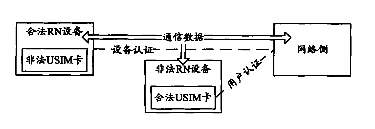
Therefore, the existing legality authentication for RN cannot guarantee that a legal USIM card is inserted into a legal RN device, that is, the user authentication of RN and the binding of devices cannot be realized, so that the communication data security between RN and the network side cannot be guaranteed

Method used


Image

  • Method and system for generating safety key bound with device
  • Method and system for generating safety key bound with device
  • Method and system for generating safety key bound with device

Examples


Embodiment Construction

[0042] Figure 4 A flowchart of a method for generating a security key bound to a device for the present invention, such as Figure 4 shown, including the following steps:

[0043] Step 400: The network side agrees with the RN on user security keys and device-related security parameters.

[0044] In this step, the method for agreeing on the user security key between the network side and the RN can adopt the existing EPSAKA process, and the specific implementation will not be repeated here. In this case, the network side refers to the MME. Among them, the user security key includes: the intermediate key K agreed in the EPS AKA process ASME ; or, by the intermediate key K ASME Derived other keys, such as the base station key K eNB or NH value.

[0045] In this step, the method for the network side and the RN to negotiate device-related security parameters includes:

[0046] The network side initiates an authentication process to the RN, and during the authentication proce...


PUM


Abstract

The invention discloses a method and a system for generating a safety key bound with a device. The method comprises the following steps of: a network side and a relay node (RN) reach an agreement on the user safety key and device-dependent safety parameters; and the network side notifies the RN to generate the safety key bound with the device, and the RN generates the safety key bound with the device and responds to the network side according to the user safety key and device-dependent safety parameters. Through the method and the system, the safety key bound with the device is generated, an attracter is prevented from wiretapping and falsifying communication data by using illegal equipment, and the safety of the communication data between the RN and the network side is ensured.

Description

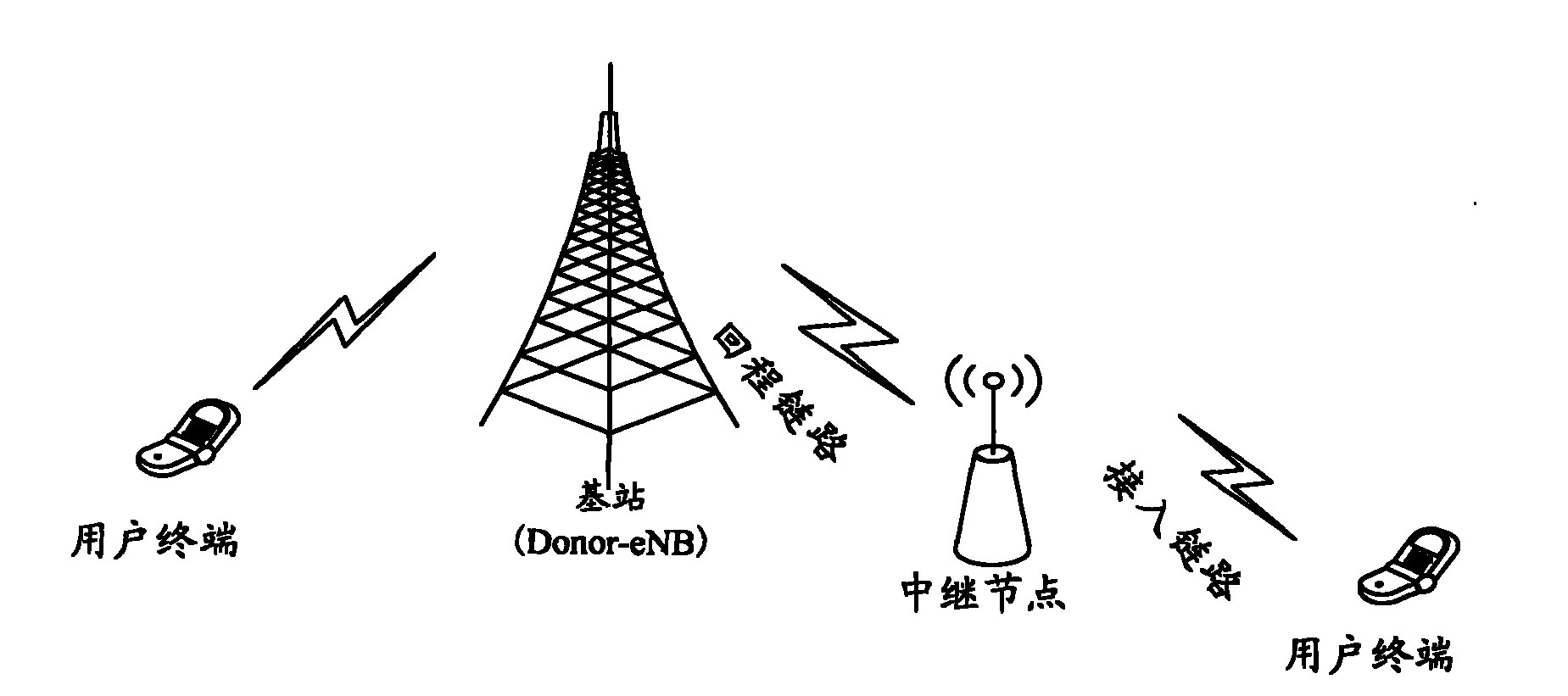
technical field [0001] The invention relates to a security authentication technology in an LTE network, in particular to a method and a system for generating a security key bound with equipment. Background technique [0002] figure 1 It is a schematic diagram of the composition structure of the Long Term Evolution (LTE, Long Term Evolution) network, such as figure 1 As shown, the LTE network is composed of Evolved Universal Terrestrial Radio Access Network (E-UTRAN, Evolved Universal Terrestrial Radio Access Network) and Evolved Packet Switching Center (EPC, Evolved Packet Core), and the network is flat. EUTRAN is connected with EPC through S1 interface. [0003] Among them, EUTRAN is composed of multiple interconnected evolved base stations (eNB, Evolved NodeB), and each eNB is connected through the X2 interface; EPC is composed of a mobility management entity (MME, MobilityManagement Entity) and a serving gateway entity (S-GW, Serving Gateway) composition. In addition,...

Claims


Application Information

Patent Timeline
IPC IPC(8): H04W12/04H04W12/06H04W28/18H04W12/041H04W12/48
Inventor 和峰甘露
Owner ZTE CORP
Learn More