
Intelligent submarine cable with invisibly implanted sensing fiber in cable core insulating layer

A technology for sensing optical fibers and submarine optical cables, which is applied in the directions of light guides, optics, and optical components. The effect of eavesdropping

Active Publication Date: 2015-11-11
江苏通光海洋光电科技有限公司
View PDF6 Cites 17 Cited by
  • Summary
  • Abstract
  • Description
  • Claims
  • Application Information

AI Technical Summary

Problems solved by technology

[0005] 1) Use the existing communication optical fiber in the cable to form a distributed sensing system, but since the communication optical fiber in the optical cable is in the center and protected by multiple structures, unless the optical fiber attenuation increases or breaks, it will affect the deformation of the cable itself (or Strain) is not sensitive, the external signal received when used to monitor the surrounding environment information will be very weak, it is difficult to accurately and reliably judge the disturbance and eavesdropping around the optical cable
[0006] 2) Install various photoelectric sensors (similar to splice boxes of submarine optical cables) protected by pressure-resistant housings at intervals (for example, 1,000 meters) on the submarine cable line. Although the sensitivity of these sensors can be very high, they include The pressure-resistant shell of the sensor destroys the continuity of the submarine optical cable and has a large self-monitoring blind zone (the cable section between the two sensors, so it is not distributed), because the shell is exposed to the light and the appearance is large, Provides an opportunity for eavesdroppers to find and open these housings to expose the fiber optics

Method used


Image

  • Intelligent submarine cable with invisibly implanted sensing fiber in cable core insulating layer

Examples


Embodiment Construction

[0020] In order to deepen the understanding of the present invention, the present invention will be further described below in conjunction with the embodiments and accompanying drawings. The embodiments are only used to explain the present invention and do not constitute a limitation to the protection scope of the present invention.

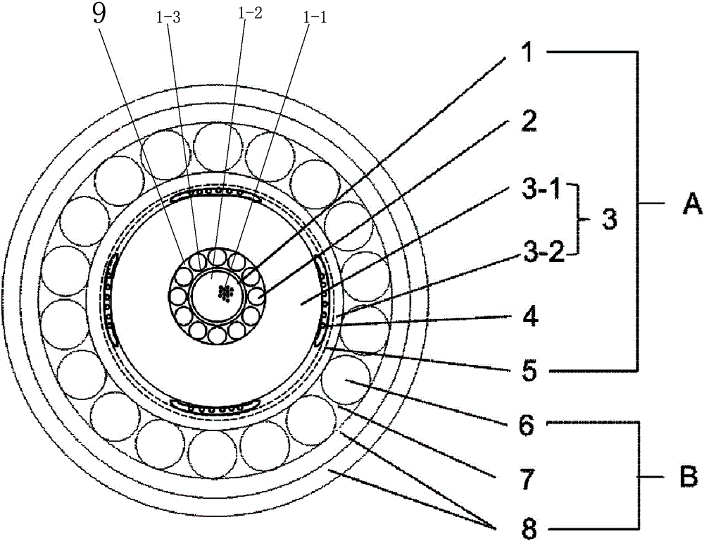
[0021] Such as figure 1 As shown, a kind of intelligent submarine optical cable of the present invention in which the sensing optical fiber is implanted invisible in the cable core insulating layer, it comprises a cable core A, a sensing optical fiber 4 and an outer armor strengthening protection layer B, and the cable core A has an insulating sheath Layer 3, the insulating sheath 3 is divided into an inner insulating layer 3-1 and an outer insulating layer 3-2, and the sensing optical fiber 4 is invisible implanted between the inner insulating layer 3-1 and the outer insulating layer 3-2, and the sensing optical fiber 4 Wrap on the inner insulat...


PUM


Abstract

The invention discloses an intelligent submarine cable with an invisibly implanted sensing fiber in a cable core insulating layer. The intelligent submarine cable comprises a cable core, a sensing fiber and an outer armor strengthening protective layer. The cable core comprises an insulating sheath. The insulating sheath is divided into an inner insulating layer and an outer insulating layer. The sensing fiber is invisibly implanted between the inner insulating layer and the outer insulating layer. The sensing fiber wraps the inner insulating layer with appropriate pitch and is wound and bound through gauze bundling. The sensing fiber which is invisibly implanted in the insulating sheath is used with a suitable detection instrument and system to carry out distributed online monitoring on the position movement of the cable and shape strain of bending, torsion and the like of the cable body, and sensitively detect the information of water sound, seismic waves, boat approaching, anchor hooking and the like within a certain range from the submarine cable. Due to the fact that the sensing fiber is invisibly implanted in the cable core insulating layer and is adhered with the insulating layer, the behavior of cable core stripping can be timely identified, and communication fiber intercepting is effectively prevented. The anti-intercepting intelligent submarine cable integrates communication and sensing.

Description

technical field [0001] The invention relates to a submarine optical cable, in particular to an intelligent submarine optical cable in which a sensing optical fiber is implanted invisible in a cable core insulating layer. Background technique [0002] The working environment of the submarine optical cable is very complicated, and it is easy to change its position due to the influence of water flow, and it is deformed by pulling, torsion, kink, etc. due to ship navigation and fishery and aquaculture activities (such as anchor hooking, etc.), which will reduce the quality of the transmission signal and The life of the optical cable will be severe, and it will cause fiber breakage and cable breakage in severe cases. [0003] Submarine optical cable systems carry massive amounts of information, but submarine optical cables can be tapped. At present, the main method of eavesdropping on submarine optical cables is to strip off all the protective structures to expose the optical fi...

Claims


Application Information

Patent Timeline
IPC IPC(8): G02B6/44
CPCG02B6/4403G02B6/4415G02B6/4427G02B6/443
Inventor 徐军黄俊华林剑黄卓杰范健生丁国锋
Owner 江苏通光海洋光电科技有限公司
Learn More