
Power supply circuit of light-emitting diode

A technology of light emitting diodes and power supply circuits, which is applied in the directions of electric lamp circuit layout, circuit layout, light source, etc., can solve the problems of high power conversion loss, poor efficiency, and increased cost of power supply circuits, so as to reduce power conversion loss, improve efficiency, cost reduction effect

Active Publication Date: 2013-04-17
DELTA ELECTRONICS INC
View PDF2 Cites 0 Cited by
  • Summary
  • Abstract
  • Description
  • Claims
  • Application Information

AI Technical Summary

Problems solved by technology

[0007] The main purpose of the present invention is to provide a power supply circuit for light-emitting diodes to solve the traditional power supply circuit that needs to convert the received electric energy into a high-level voltage to drive the light-emitting diode components to light up. The power supply circuit has high power conversion loss and poor efficiency. At the same time, the components in the post-stage conversion circuit need to select components with high withstand voltage ratings, which leads to a relatively high cost of the power supply circuit.

Method used


Image

  • Power supply circuit of light-emitting diode
  • Power supply circuit of light-emitting diode
  • Power supply circuit of light-emitting diode

Examples


Embodiment Construction

[0051] Some typical embodiments embodying the features and advantages of the present invention will be described in detail in the description in the following paragraphs. It should be understood that the present invention can have various changes in different ways without departing from the scope of the present invention, and that the description and drawings therein are illustrative in nature rather than limiting the present invention.

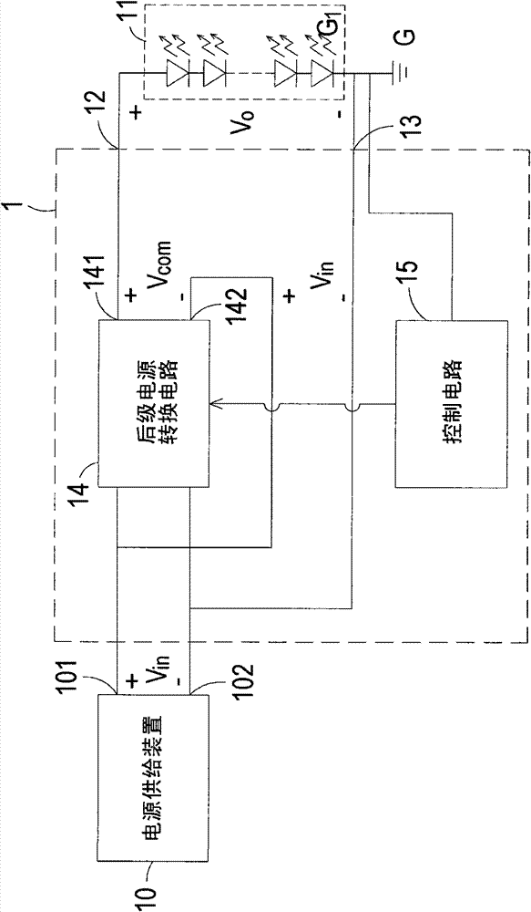
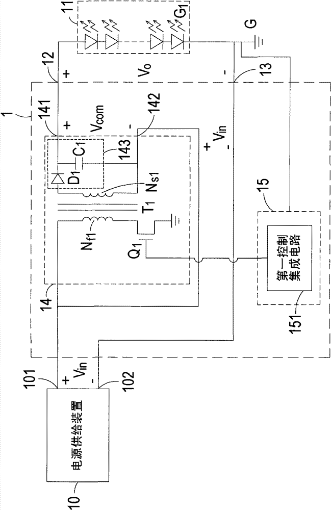
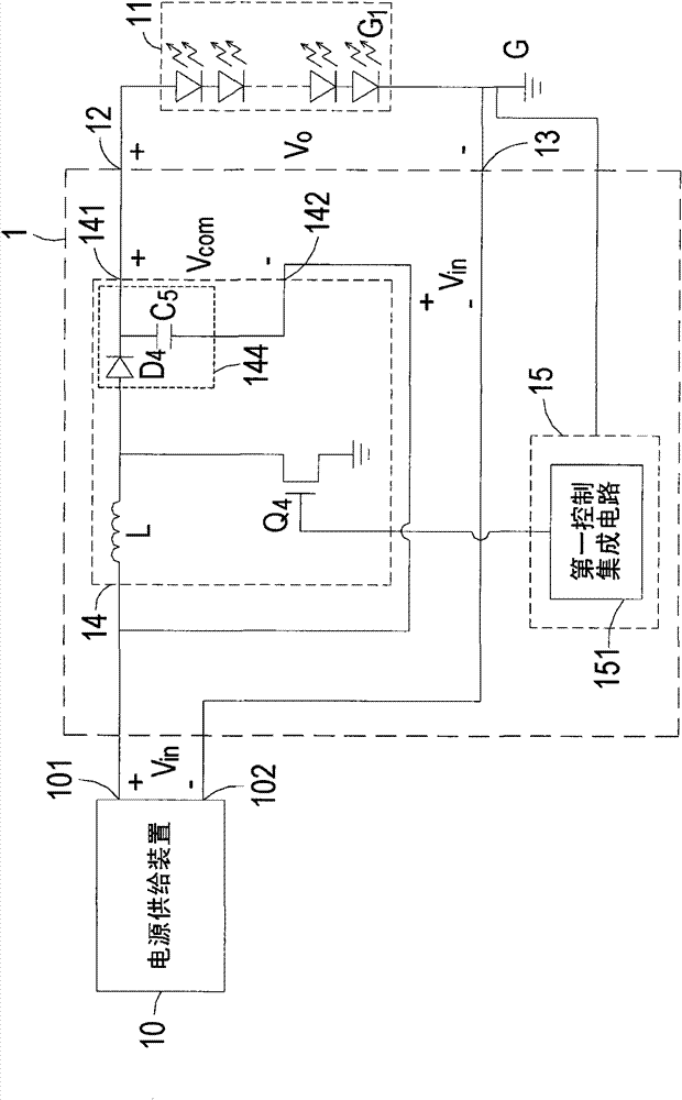
[0052] see figure 1 , which is a circuit block diagram of a power supply circuit in a preferred embodiment of the present invention. like figure 1 As shown, the power supply circuit 1 of this embodiment receives an input voltage V through a first positive output terminal 101 and a first negative output terminal 102 of a power supply device 10 in , and output a drive voltage V o Give at least one light emitting diode assembly 11 to drive the light emitting diode assembly 11 to light up, wherein the light emitting diode assembly 11 can be, b...


PUM


Abstract

The invention discloses a power supply circuit of a light-emitting diode. A first positive output end and a first negative output end of a power source supply device are used for receiving input voltages and outputting drive voltages to a light-emitting diode component. The power supply circuit comprises a second positive output end, a second negative output end, a post-state power source conversion circuit and a control circuit, wherein the second positive output end and the second negative output end are connected with the light-emitting diode component, and the second negative output end is connected with the first negative output end; the post-stage power source conversion circuit is used for converting the input voltages into compensating voltages and is provided with a third positive output end connected with the second positive output end and a third negative output end connected with the first positive output end; and the control circuit is connected with the post-stage powersource conversion circuit and the light-emitting diode component and is used for detecting and controlling the current of the light-emitting diode component, wherein the drive voltage is obtained by adding the input voltage and the compensating voltage. The power supply circuit improves efficiency because of a little electric energy conversion loss, and because elements with low voltage-resistinglimit can be selected as the elements in the post-stage power source conversion circuit, the cost is reduced.

Description

technical field [0001] The invention relates to a power supply circuit, in particular to a light-emitting diode power supply circuit capable of reducing power conversion loss. Background technique [0002] In recent years, due to breakthroughs in light emitting diode (Light Emitting Diode, LED) manufacturing technology, the luminous brightness and luminous efficiency of light emitting diodes have been greatly improved, thus making light emitting diodes gradually replace known lamp tubes and become new lighting components, widely used in For example, lighting applications such as household lighting devices, automotive lighting devices, handheld lighting devices, LCD panel backlights, traffic sign lights, and signage boards. [0003] In order to increase the brightness of the LEDs, usually a plurality of LEDs are connected in series to form an LED module. However, due to the relationship between the LED technology, the start-up voltage of each LED will not be exactly the same...

Claims


Application Information

Patent Timeline
Patent Type & Authority Patents(China)
IPC IPC(8): H05B37/00H05B37/02F21V23/00F21Y101/02
Inventor 黄仲才李柏毅颜上进
Owner DELTA ELECTRONICS INC
Learn More