
Flow sampling device

A sampling device and flow technology, applied in the field of medical devices, can solve the problems of easy accumulation of water in the sampling tube, wrong measurement values, poor ventilation, etc., and achieve the effect of high measurement accuracy

Inactive Publication Date: 2011-01-05
BEIJING AEONMED
View PDF4 Cites 3 Cited by
  • Summary
  • Abstract
  • Description
  • Claims
  • Application Information

AI Technical Summary

Problems solved by technology

[0004] The purpose of the present invention is to provide a flow sampling device, which can solve the problem that the sampling tube connected to the patient end or a place very close to the patient is prone to water accumulation, and the longer sampling hose will cause poor ventilation during use, so that the provided Problems with incorrect or deviating measurements to physicians

Method used


Image

  • Flow sampling device
  • Flow sampling device
  • Flow sampling device

Examples


Embodiment Construction

[0017] The present invention will be described in detail below with reference to the accompanying drawings and in combination with embodiments.

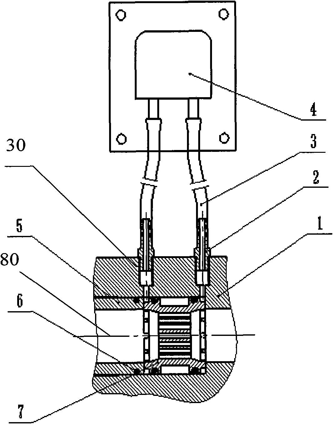
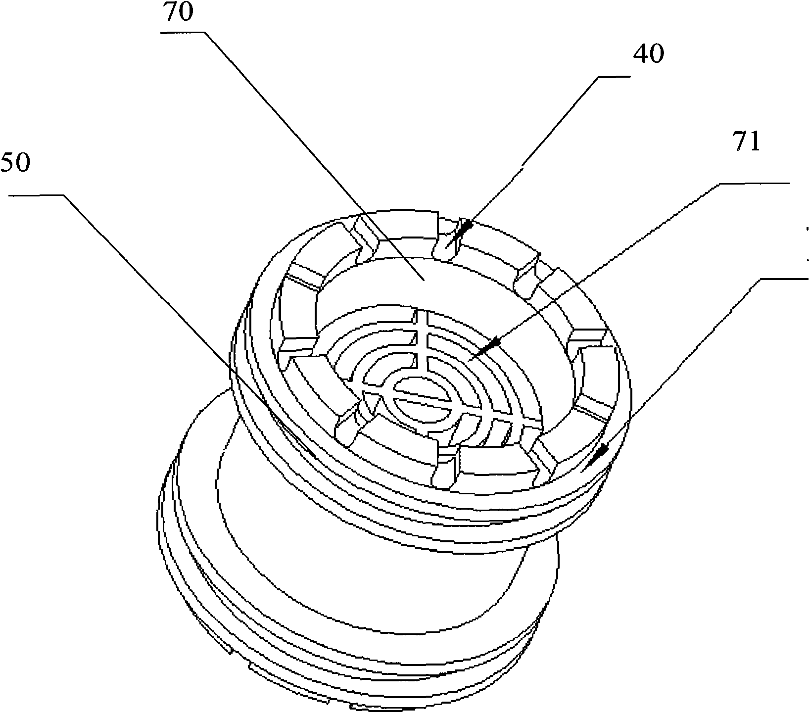
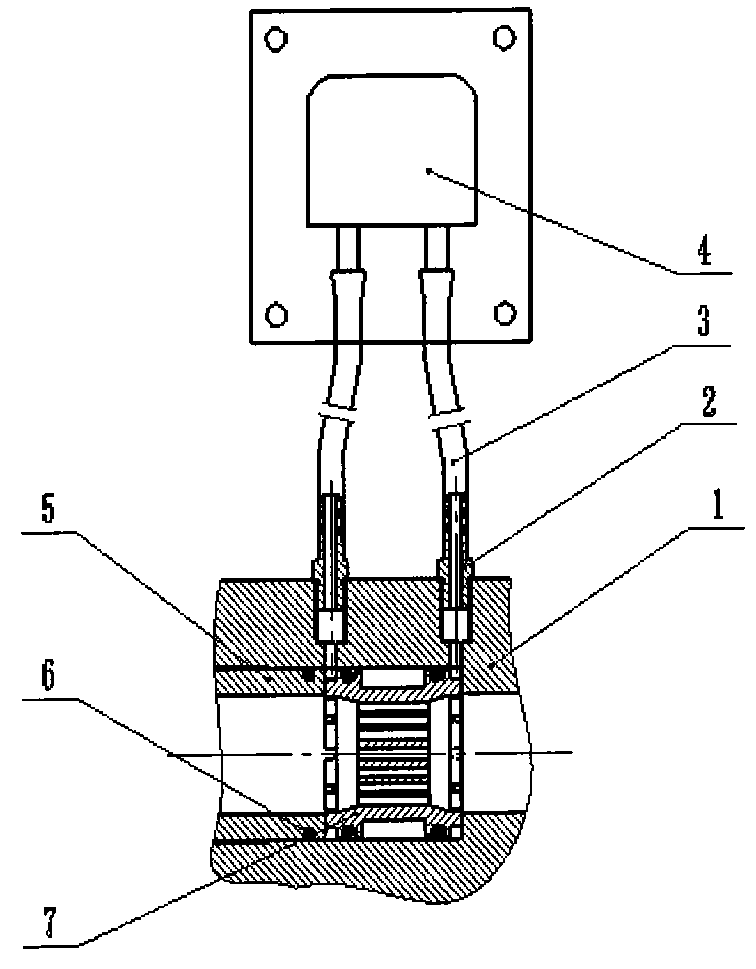
[0018] figure 1 The cross-sectional structure of the flow sampling device according to the present invention is schematically shown. figure 2 The structure of the gas resistance element of the flow sampling device according to the present invention is schematically shown. As shown in the figure, the flow sampling device according to the present invention includes: a sampling circuit 5, 7, 1, which includes a blocking member 5 for blocking the air resistance member 7 to prevent the air resistance member 7 from moving, and has a through hole 80 , an annular groove is provided on its side wall, and an air resistance member 7 has a through hole 70 in the middle, so that the gas can pass through it, and it is closely connected with the blocking part 5, and a plurality of U-shaped grooves 40 are opened on the edges of its two ends, so th...


PUM

PropertyMeasurementUnit
Lengthaaaaaaaaaa

Abstract

The invention provides a flow sampling device which comprises a sampling loop, a probe part, a sampling sensor and a hose, wherein the sampling loop comprises a stopper, an air stopper and a shell; the stopper comprises a through hole; the side wall of the stopper is provided with an annular groove; the air stopper is closely connected with a stopping part; the edges of two end faces of the air stopper are provided with a plurality of U-shaped grooves; the side wall of the air stopper is provided with a plurality of annular grooves; the stopper and the air stopper are closely contained in the shell; a through hole is arranged on the shell and communicated with the air stopper; the probe part is arranged in the through hole of the shell; and one end of the hose is connected with he sampling sensor while the other end is connected with the probe part. According to the flow sampling device, the sampling position is adjusted, the length of a sampling hose is shortened, a new calibration way and a new connection way are adopted, and the problems that a measured value provided for a doctor is wrong or deviated from an actual value and the like as a sampling tube accessed to a patient or a place near the patient accumulates water easily and the relatively long sampling hose generates unsmooth ventilation in the use process are overcome. Therefore, the effect of relatively high measurement precision is achieved.

Description

technical field [0001] The invention relates to the field of medical equipment, in particular to a flow sampling device. Background technique [0002] Traditional anesthesia machine sampling and measurement devices usually connect the sampling hose to the patient end or a position close to the patient, and the sampling hose is relatively long. [0003] In the process of realizing the present invention, the inventor has found that there are at least the following problems in the prior art: because the sampling tube connected to the patient end or very close to the patient is prone to water accumulation, the longer sampling hose will produce Inadequate ventilation such that measurements given to physicians are false or deviate from actual values. Contents of the invention [0004] The purpose of the present invention is to provide a flow sampling device, which can solve the problem that the sampling tube connected to the patient end or a place very close to the patient is p...

Claims


Application Information

Patent Timeline
IPC IPC(8): A61M16/00A61B10/02
Inventor 龚家明张凯牛世腾
Owner BEIJING AEONMED
Learn More