Cloth rewinder tension force adjusting framework

A tension adjustment, cloth rolling machine technology, applied in the direction of winding strips, textiles and papermaking, knitting, etc., can solve the problems of shifting to one side of the cloth winding shaft, belt wear, insufficient friction between the belt and the pulley, etc.

Inactive Publication Date: 2011-01-05
PAI LUNG MACHINERY MILL CO LTD
View PDF3 Cites 8 Cited by
  • Summary
  • Abstract
  • Description
  • Claims
  • Application Information

AI Technical Summary

Problems solved by technology

[0003] 1. Since the whole bundle of fabric on the cloth roll rod is pressed down on the first and second cloth guide shafts, when the cloth rolls more and more on the cloth roll rod, the cloth becomes heavier and will affect the lower pressure of the first and second cloth guide shafts. As the pressure increases, the fabric becomes tighter and tighter, resulting in uneven tightness
[0004] 2. Because the cloth roll rod is only embedded in the guide rail, its connection effect is poor. During the cloth roll operation, if the cloth roll rod is easy to be thrown out during the operation of the machine, it will cause danger
[0005] 3. The amount of cloth storage that this patent application can provide is small, about 20kg, which causes inconvenience in dyeing and finishing, and produces more than waste
[0007] 1. At the initial stage of cloth rolling, in order to ensure that the cloth winding shaft can wind up the fabric tightly, the belt and pulley that drive the cloth winding shaft must be tightened so that the cloth winding shaft has a greater rolling force to wind the cloth tightly. However, the belt and When the pulley is in operation, it is in a tight state for a long time, and the belt is prone to wear and tear, resulting in a short service life of the belt. Frequent replacement of the belt will increase the maintenance cost and time, which is not economical.
[0008] 2. On the bearing, after long-term use, the belt is worn out due to the tight state, which will cause insufficient friction between the belt and the pulley and easy to slip, resulting in insufficient initial winding force of the cloth winding shaft, thus causing The fabric on the cloth winding shaft is too loose and it is easy to shift when the cloth winding machine is running at high speed. When the cloth is rolled and thicker, it will be shifted to one side of the cloth winding shaft by the operation of the random table, so that the machine cannot maintain balance and Abnormal cloth winding occurs, and finally causes the machine to stop running

Method used


Image

  • Cloth rewinder tension force adjusting framework
  • Cloth rewinder tension force adjusting framework
  • Cloth rewinder tension force adjusting framework

Examples


Embodiment Construction

[0018] Relevant detailed description and technical contents of the present invention are as follows now in conjunction with the accompanying drawings:

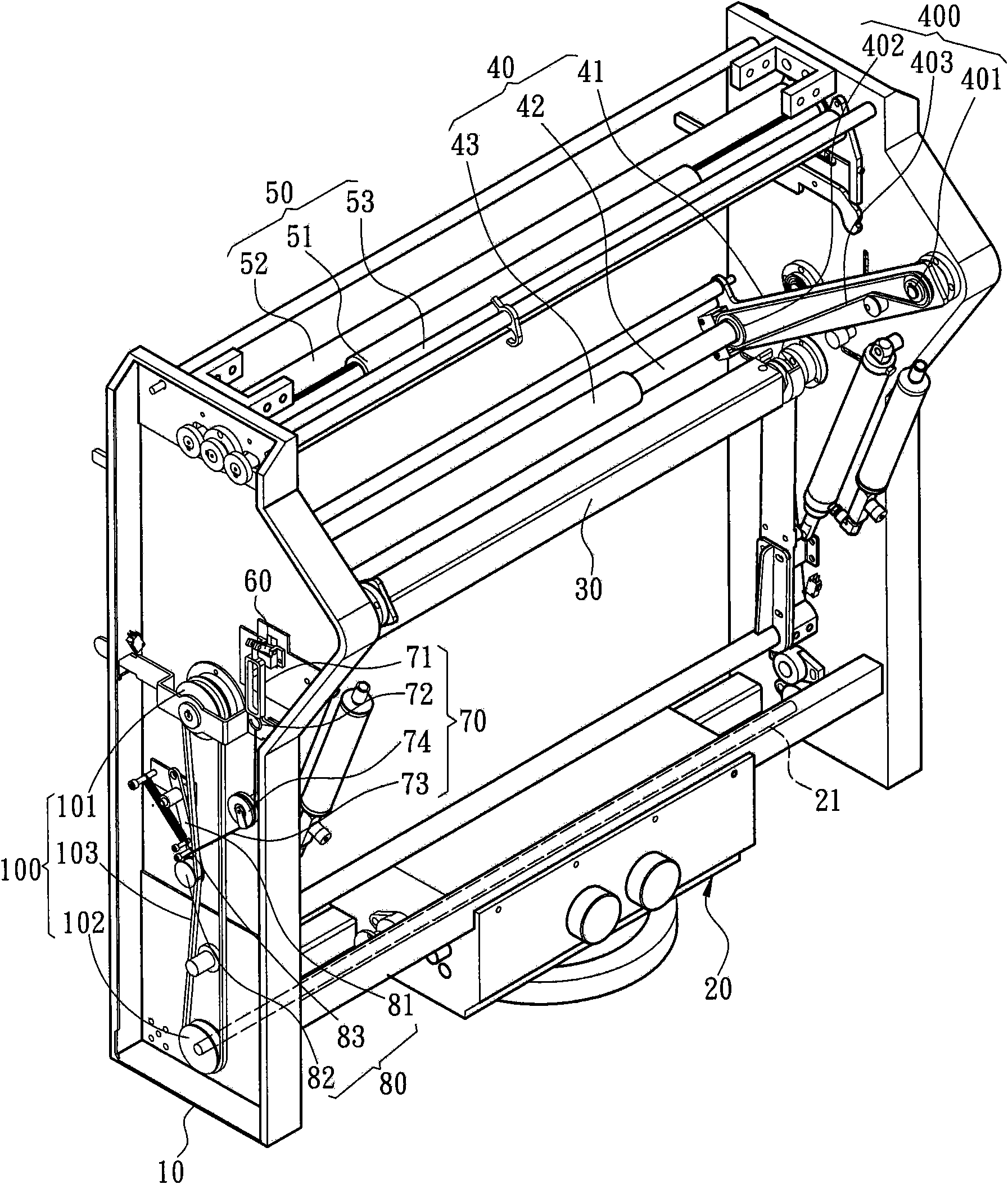
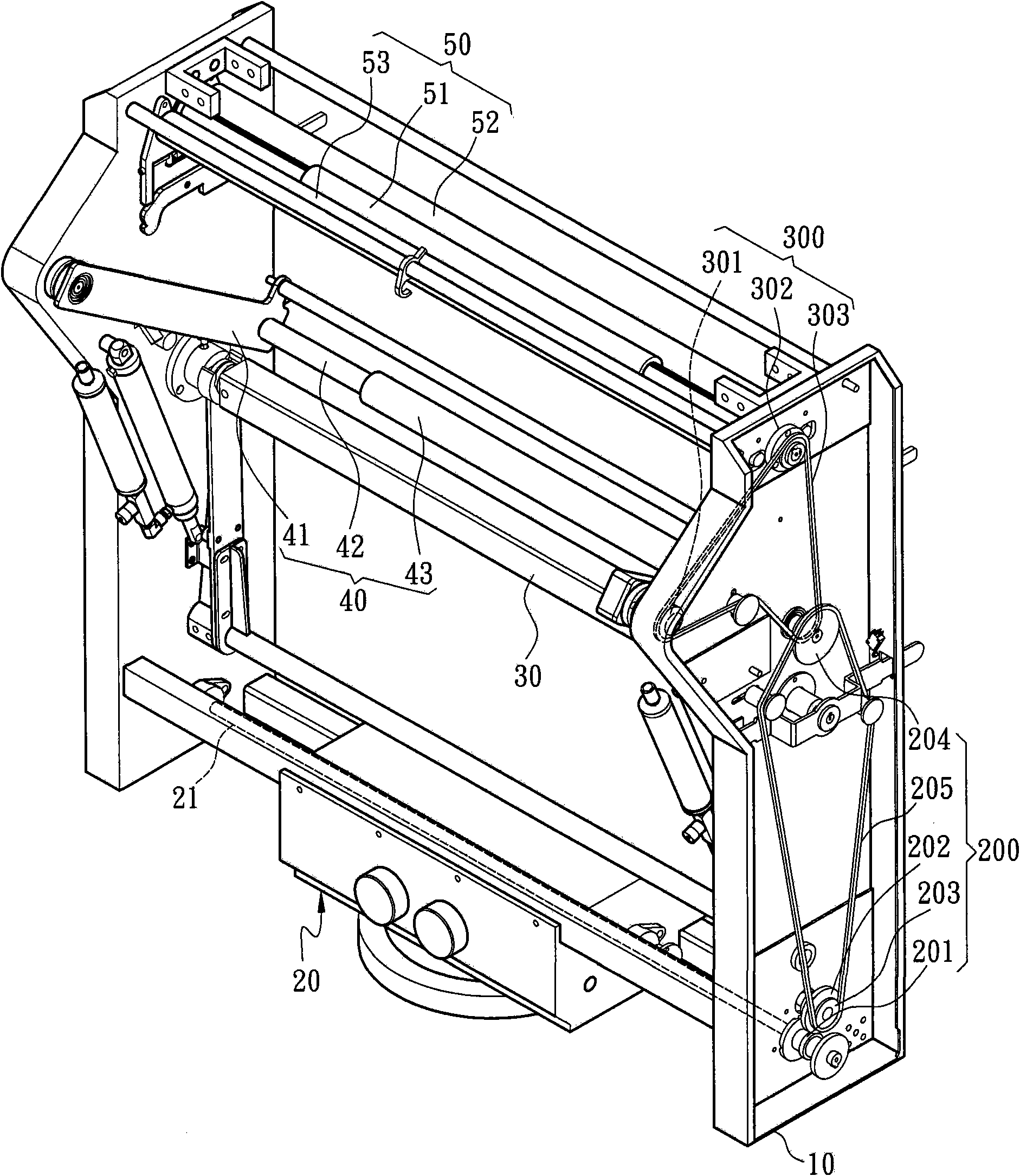
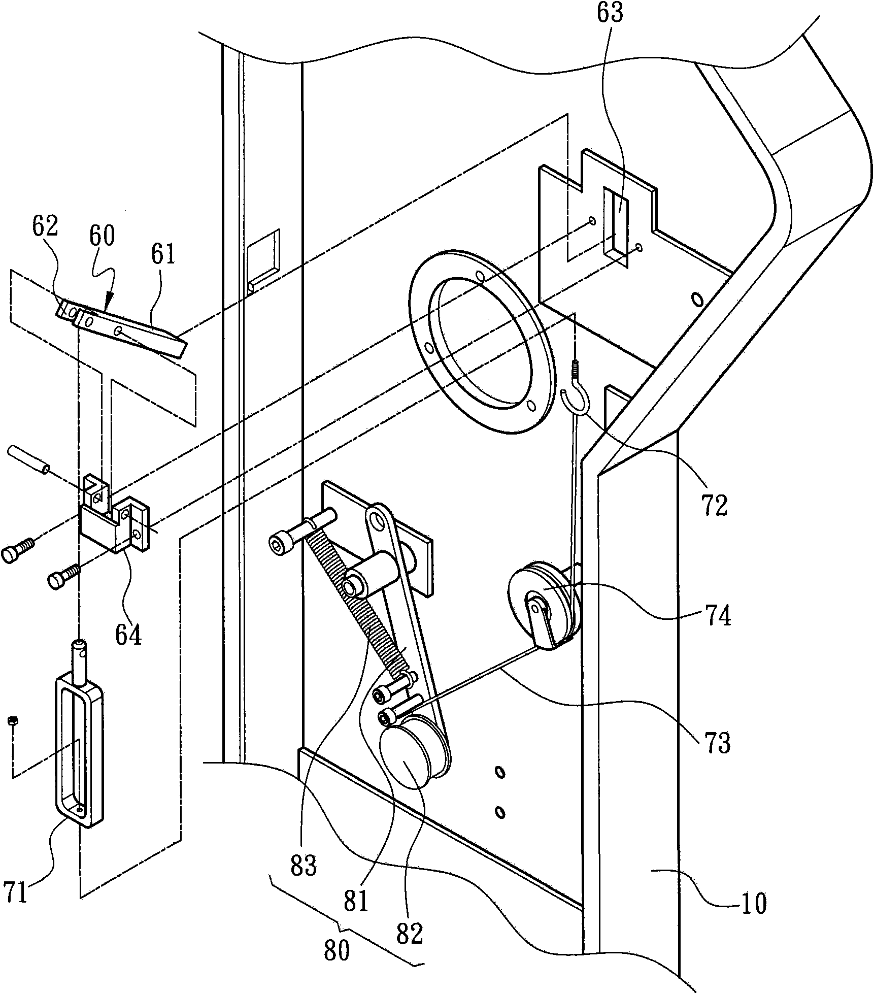
[0019] refer to figure 1 and figure 2 As shown, the present invention is a tension adjustment structure of a cloth winding machine, the cloth winding machine includes two side boxes 10, and a driving mechanism 20 and a cloth winding bar 30 are arranged between the two side boxes 10 from bottom to top. , a cloth pressing mechanism 40 and a cloth feeding mechanism 50, and the side box 10 is also provided with an adjustment mechanism between the driving mechanism 20 and the cloth pressing mechanism 40. The action of the mechanism 40 is used to adjust the cloth-rolling tension of the cloth-rolling rod 30; wherein, the driving mechanism 20 is arranged at a position close to the bottom between the two side boxes 10, and a shaft 21 is extended from the inside, and the shaft The two ends of 21 penetrate to the inside of the two sid...


PUM


Abstract

The invention discloses a cloth rewinder tension force adjusting framework comprising a driving mechanism, a cloth winding rod, a cloth pressing mechanism and an adjusting mechanism, wherein the driving mechanism is arranged on the cloth rewinder; the cloth winding rod and the driving mechanism are provided with corresponding driving wheels on which belts are straddled to cause the driving mechanism to drive the cloth winding rod to furl cloth; the cloth pressing mechanism is provided with an action arm and a cloth pressing rod, wherein the action arm is arranged on the cloth rewinder, and the cloth pressing rod is arranged on the action arm; the cloth pressing rod is provided with a first position which does not contact with the cloth, and a second position which contacts with the cloth and is supported by the cloth; the adjusting mechanism is pressed by the action arm on the first position of the cloth pressing rod so as to abut against the belt to increase the initial driving force for the cloth winding rod to coil cloth; the second position of the cloth winding rod is driven by the action arm to separate from the belt; and the cloth is under the active control of the cloth pressing rod to obtain the effect of consistent compactness of the cloth, thus improving cloth coiling quality.

Description

technical field [0001] The invention relates to a tension adjustment structure of a cloth rolling machine, in particular to a tension adjustment structure applied to a high-speed high-speed cloth rolling machine to control the rolling tightness of the cloth when the cloth is initially rolled. Background technique [0002] At present, the cloth woven by the knitting machine is rolled into a bundle by a cloth roll machine, as shown in the Chinese Taiwan Patent Application No. M243472, which discloses an improved structure of the guide shaft of the cloth roll machine. The cloth roll machine has There are two side cabinets, and there are two guide rails extending upwards on the inner side of the middle section of the two side cabinets, which can be used for placing the two ends of a cloth roll rod respectively, and there are two horizontally extending parallel to each other below the two guide rails. The first cloth guide shaft and the second cloth guide shaft, when the cloth wi...

Claims


Application Information

Patent Timeline
Patent Type & Authority Applications(China)
IPC IPC(8): B65H18/10B65H18/26B65H23/26D04B37/00
Inventor 陈世基
Owner PAI LUNG MACHINERY MILL CO LTD
Why Eureka
Try Eureka