Eureka AIR delivers breakthrough ideas for toughest innovation challenges, trusted by R&D personnel around the world.

Fan without fan blades

A fanless, fanless technology, applied in non-variable-capacity pumps, pump devices, machines/engines, etc., can solve the problems of large volume and occupied space, affecting use, etc., to achieve compact structure and small occupied space. , the effect of large airflow

Inactive Publication Date: 2011-01-05
任文华
View PDF1 Cites 128 Cited by
  • Summary
  • Abstract
  • Description
  • Claims
  • Application Information

AI Technical Summary

Problems solved by technology

[0003] Since the components used to generate high-pressure airflow through the nozzles of this kind of fan are located outside the closed loop formed by the nozzles, the volume and the occupied space are relatively large, which affects its use.

Method used


Image

  • Fan without fan blades
  • Fan without fan blades
  • Fan without fan blades

Examples


Embodiment Construction

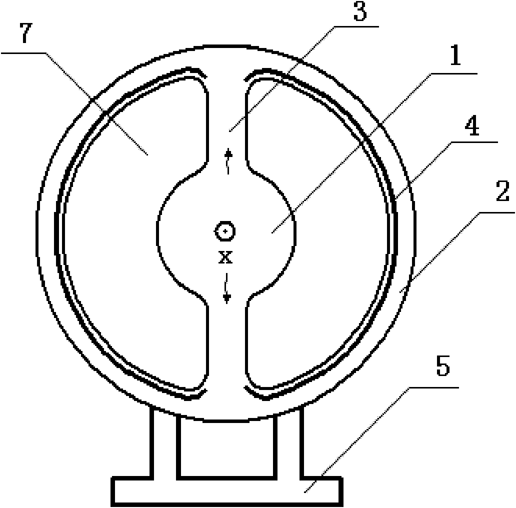
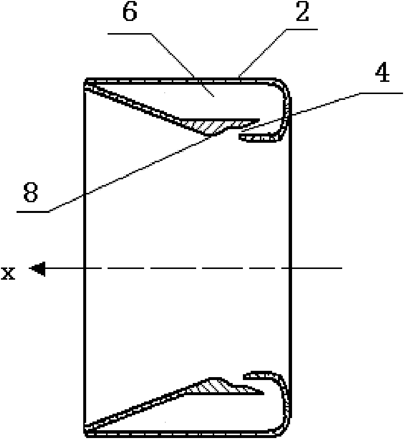
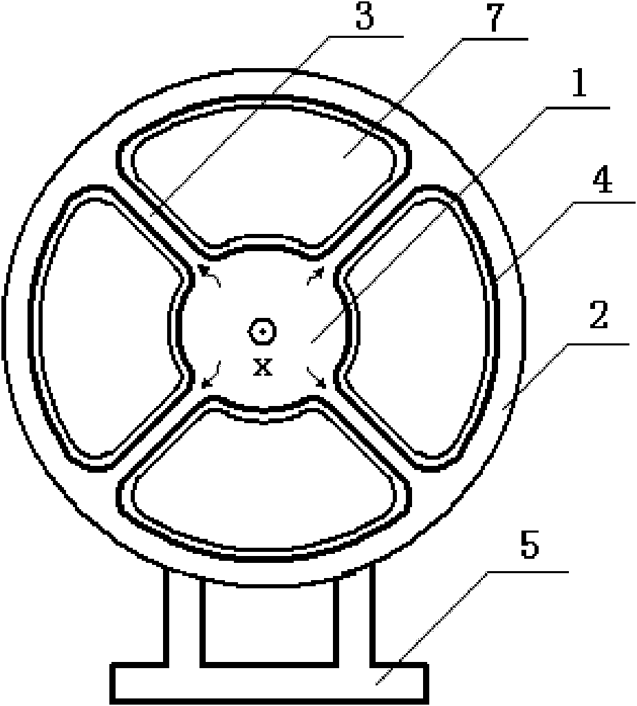
[0028] figure 1 It is a schematic diagram of the bladeless fan of the present invention. The device of the present invention includes: an airflow generating device 1, a nozzle 2 and a connecting pipe 3, and refer to figure 2 , the nozzle 2 includes an internal channel 6, an exhaust port 4 and a Coanda surface 8 arranged near the exhaust port 4, the nozzle 2 forms a circular closed loop with the axis X as the axis of symmetry, and the airflow generating device 1 is centered on the axis X X is the axis of symmetry and is completely located in the circular closed loop formed by the nozzle 2. The two connecting pipes 3 are respectively connected between the airflow generating device 1 and the nozzle 2. The nozzle 2 is fixed on the bracket 5. The airflow generating device 1 , the nozzle 2 and the two connecting pipes 3 define two openings 7 through which the air outside the fan is sucked by the high-pressure airflow injected from the exhaust port 4 .

[0029] When this kind of f...


PUM

PropertyMeasurementUnit
Widthaaaaaaaaaa

Abstract

The invention discloses a fan without fan blades and relates to a fan device, which is characterized by comprising an airflow generating device (1), a nozzle (2) and a connecting pipe (3), wherein the nozzle comprises an internal channel (6), an exhaust port (4) and a closed loop, the airflow generating device is used for producing high-pressure airflow, at least part of the airflow generating device is positioned in the closed loop of the nozzle, and the connecting pipe is connected between the airflow generating device and the nozzle, thereby being a channel for circulation of the high-pressure airflow from the airflow generating device to the nozzle. The device has compact structure and low noise and can provide the airflow with uniform flow rate.

Description

technical field [0001] The invention relates to a fan device for generating air flow. Background technique [0002] The Chinese patent application with publication number CN 101424279A (Application No.: 200810177844.8) published on May 6, 2009 discloses a fan for generating air flow, which includes nozzles and components for generating high-pressure airflow through the nozzles, Said member is located outside a closed loop formed by said nozzle comprising an internal channel, an exhaust port for receiving air flow from the internal channel, and a Coanda surface located immediately adjacent to the exhaust port, the exhaust port being located into directing airflow over the Coanda surface. This kind of fan does not need to have fan blades to generate relatively uniform airflow and bring cooling effect. [0003] Since the fan is used to generate the high-pressure airflow passing through the nozzle, it is located outside the closed loop formed by the nozzle, so its volume and o...

Claims


Application Information

Patent Timeline
IPC IPC(8): F04F5/16F04F5/46F04F5/44
CPCF04D25/08F04F5/16
Inventor 任文华
Owner 任文华
Why Eureka
Eureka Blog
Learn More