Autonomic multi-mode management method

A multi-modal and modal technology, applied in the direction of program control devices, etc., can solve problems such as low conversion efficiency

Inactive Publication Date: 2014-07-30
NORTHWESTERN POLYTECHNICAL UNIV
View PDF2 Cites 0 Cited by
  • Summary
  • Abstract
  • Description
  • Claims
  • Application Information

AI Technical Summary

Problems solved by technology

[0004] In order to overcome the deficiency of low conversion efficiency in the prior art, the present invention provides an autonomous multi-modal management method for intelligent embedded systems

Method used


Image

  • Autonomic multi-mode management method
  • Autonomic multi-mode management method
  • Autonomic multi-mode management method

Examples


Embodiment Construction

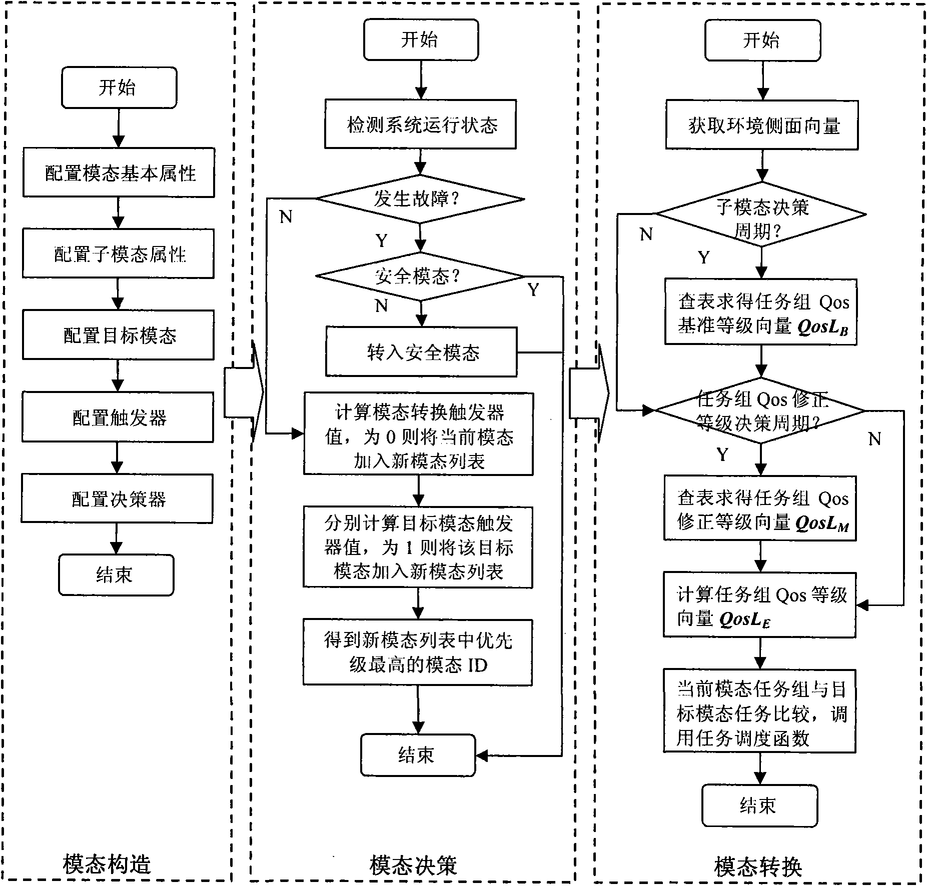
[0054] figure 1 The multimodal autonomic management execution flow of the present invention is described. The present invention has been successfully implemented in the autonomous mobile robot computing platform, and the specific implementation steps are as follows:

[0055] Step 1: Modal representation and construction.

[0056] Step 11: Configure the basic properties of the modal, including modal ID, modal name, modal type and modal priority, such as figure 1 shown. In this example, the system has 6 modes in total, and the mode ID ranges from 0 to 5. The modal names are initial modal, termination modal, cruise modal, search modal, tracking modal and safe modal. Among them, cruise, search and track are mission modes, and the other three modes are special modes. The 6 mode priorities are set to 0, 0, 0, 1, 2, 3 respectively, and the security mode has the highest priority;

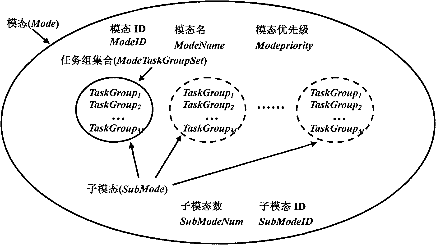
[0057] Step 12: Configure submodal properties, such as figure 2 shown. Sub-modals are secondary...


PUM


Abstract

The invention discloses an autonomic multi-mode management method, which comprises the following steps of: constructing a five-tuple representation mode comprising mode basic information, sub-mode information, target mode information, a mode trigger and a mode decider; deciding the mode ID of the current system operation by adopting a trigger mechanism; and finally, calculating the QoS level of each task group in the mode by adopting a two-stage multi-granularity decision model, and adjusting task scheduling parameters to complete task scheduling. The method improves the mode conversion efficiency of the system and enhances the environmental adaptability of the system.

Description

technical field [0001] The invention relates to a method for autonomous multi-mode management of an intelligent embedded system. Background technique [0002] Embedded systems are now equipped with a variety of sensors, which can obtain information on simple external environments and operating objects, and are analyzed and processed by the internal computing system to control the system to perform tasks. Although such embedded systems have some intelligence and autonomy, they also require a lot of human control and coordination. [0003] In the literature "Realization of Conditioned Reflex Ability of Mobile Robots, Gu Donglei, Chen Weidong, Xi Yugeng, Robotics, 2001, Volume 23, No. 21", a reactive control method based on the "condition-reflex" mechanism was studied. This method designs a specific state A set of control rules between a specific action and a specific action, that is, a mapping relationship between the data collected by the sensor and the control output of the...

Claims


Application Information

Patent Timeline
Patent Type & Authority Patents(China)
IPC IPC(8): G06F9/44
Inventor 姚远张凯龙周兴社吴晓陆洲杨志义黄慧敏杨高演
Owner NORTHWESTERN POLYTECHNICAL UNIV
Why Eureka
Try Eureka