

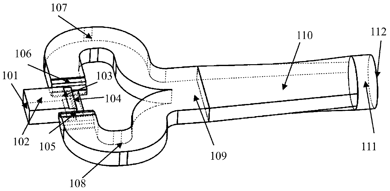
Rectangular TE10 mode to round waveguide TE21 mode converter based on H-T joint power division network
A rectangular waveguide and mode conversion technology, applied in waveguide-type devices, circuits, electrical components, etc., can solve problems such as unfavorable two-dimensional processing, complex structure of mode converters, and unfavorable application system integration, etc. compact effect
- Summary
- Abstract
- Description
- Claims
- Application Information
AI Technical Summary
Problems solved by technology
Method used
Image

Examples
Embodiment Construction
[0021] The present invention will be further described below in conjunction with embodiment. It should be noted that if the term indicates the orientation or positional relationship is based on the orientation or positional relationship shown in the drawings, or the orientation or positional relationship that is usually placed when the product of the invention is used, it is only for the convenience of describing the present invention and simplifying the Describes, but does not indicate or imply that the device or element referred to must have a specific orientation, be constructed in a specific orientation, and operate in a specific orientation, and therefore should not be construed as limiting the invention.
[0022] In addition, the terms "first", "second", "third" and so on are only used for distinguishing descriptions, and should not be understood as indicating or implying relative importance.
[0023] In the description of the present invention, it also needs to be expla...
PUM
 Abstract
Description
Claims
Application Information