Rectangular Waveguide tm11 Mode Microwave High Power Ribbon Electron Beam Collector

A rectangular waveguide, TM11 technology, applied in the field of high-power microwave, to achieve the effect of wide bandwidth, low processing cost, and insensitive structural parameters

Active Publication Date: 2016-05-18
NAT UNIV OF DEFENSE TECH
View PDF9 Cites 0 Cited by
  • Summary
  • Abstract
  • Description
  • Claims
  • Application Information

AI Technical Summary

Problems solved by technology

However, the strip electron beam microwave source is not a circular symmetric structure, and its main working mode - rectangular waveguide TM 11 Mode and Conventional High Power Microwave Sources Working Mode Circular WaveguideTM 01 Or the circular waveguide TEM mode is also significantly different, so it is difficult to directly use the traditional electron beam collector, it needs to be redesigned to efficiently recover the ribbon electron beam while ensuring the output mode of the high-power microwave source - rectangular waveguideTM 11 Efficient passage of patterns
[0005] B.E.Carlsten et al. of the Los Alamos National Laboratory in the United States have given a method that can simultaneously realize TM 11 Ribbon electron beam microwave source output structure with mode output and ribbon electron beam collection function (see "Technology Development foramm-waveSheet-BeamTraveling-waveTube", B.E.Carlsten, et.al, IEEETrans.PlasmaSci., vol33, No.1, P85~ 93.), which uses a non-overmodulated Y-shaped branch waveguide structure, only 7.5% of the bandwidth for TM 11 Mode microwaves achieve power output efficiencies of less than 97%, failing to address TM well at the same time 11 Mode Efficient Pass Through and Electron Beam Collection Two Issues

Method used


Image

  • Rectangular Waveguide tm11 Mode Microwave High Power Ribbon Electron Beam Collector
  • Rectangular Waveguide tm11 Mode Microwave High Power Ribbon Electron Beam Collector
  • Rectangular Waveguide tm11 Mode Microwave High Power Ribbon Electron Beam Collector

Examples


Embodiment Construction

[0033] Below in conjunction with accompanying drawing, structure of the present invention and working principle are specifically described:

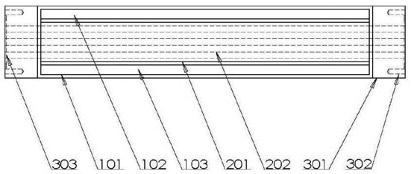
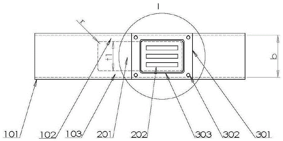
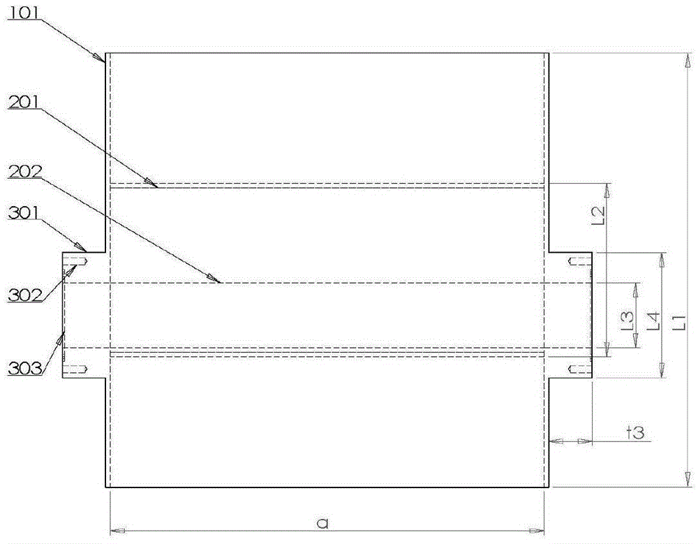
[0034] Transmission Rectangular WaveguideTM according to the present invention 11The mode microwave high-power strip-shaped electron beam collector is composed of a rectangular waveguide 101, an inner conductor 201 and two flanges 301. There are N water channels 202 inside the inner conductor 201 and the flanges 301. In this embodiment, N=3, There are four fixing screw holes 302 on the four corners of the outer end surface of the flange 301, and a sealing ring groove 303 is provided on the outer end surface; the inner conductor 201 is fixed in the axial middle of the rectangular waveguide 101, and its transverse center line The upper and lower inner walls of the rectangular waveguide 101 and the distances between the front and rear ports are equal, and the rectangular waveguide 101 is divided into an upper small waveguide 102 and a lower...


PUM


Abstract

The invention discloses a rectangular-waveguide TM11-mode microwave high-power ribbon electron beam collector, aiming to provide an electron beam collector capable of recovering a ribbon electron beam with high efficiency and good cooling performance while conducting high-efficiency transmission of a rectangular-waveguide TM11-mode microwave. The collector comprises a rectangular waveguide, an inner conductor, and two flanges. The inner conductor is a cuboid metal block fixed in the middle of a narrow edge of the rectangular waveguide and comprises cuboid water through channels inside for cooling. The flanges fixed on the outer side of the narrow edge of the rectangular waveguide communicate with the water through channels inside the inner conductor and are used for connection between the collector and an outer water tank. The collector can collect a ribbon electron beam with good cooling performance while conducting high-efficiency transmission of a rectangular-waveguide TM11-mode microwave. The collector is simple and compact in structure, low in cost, high in transmission efficiency, and wide in transmission band.

Description

technical field [0001] The invention belongs to the field of high-power microwave technology, in particular to a rectangular waveguide TM 11 Mode microwave high power ribbon electron beam collector. Background technique [0002] The application background of the present invention is a ribbon electron beam high power microwave source. Ribbon beam generally refers to an electron beam with a large aspect ratio cross-section. Strip electron beam microwave source refers to a device that utilizes the interaction between strip electron beam and microwave circuit (such as slow wave structure) to generate microwave radiation. Compared with traditional high-power microwave sources using cylindrical or hollow cylindrical electron beams, ribbon electron beam microwave sources have the advantages of low current density, high beam-wave interaction, compact structure, easy adjustment of input impedance and injection power, etc. , which is expected to become a new way to realize the engi...

Claims


Application Information

Patent Timeline
Patent Type & Authority Patents(China)
IPC IPC(8): H01J23/027H01J23/033
Inventor 杜广星马军王弘刚钱宝良袁成卫张自成李国林张强张存波杨一明
Owner NAT UNIV OF DEFENSE TECH
Why Eureka
Try Eureka