Guide structure in switching mechanism of drop-out type fuse

A drop-type fuse and guide structure technology, applied in the direction of protection switch operation/release mechanism, electrical components, circuits, etc., can solve problems such as large operating force

Inactive Publication Date: 2011-01-05
浙江赛菲特电气有限公司
View PDF0 Cites 0 Cited by
  • Summary
  • Abstract
  • Description
  • Claims
  • Application Information

AI Technical Summary

Problems solved by technology

The upper contact seat of the drop-out fuse in the prior art generally can only move up and down, and a large operating force is required when the fuse-carrying parts are closed and opened.

Method used


Image

  • Guide structure in switching mechanism of drop-out type fuse
  • Guide structure in switching mechanism of drop-out type fuse
  • Guide structure in switching mechanism of drop-out type fuse

Examples


Embodiment Construction

[0013] The technical solution of the present invention is described below by specific embodiments in conjunction with the accompanying drawings:

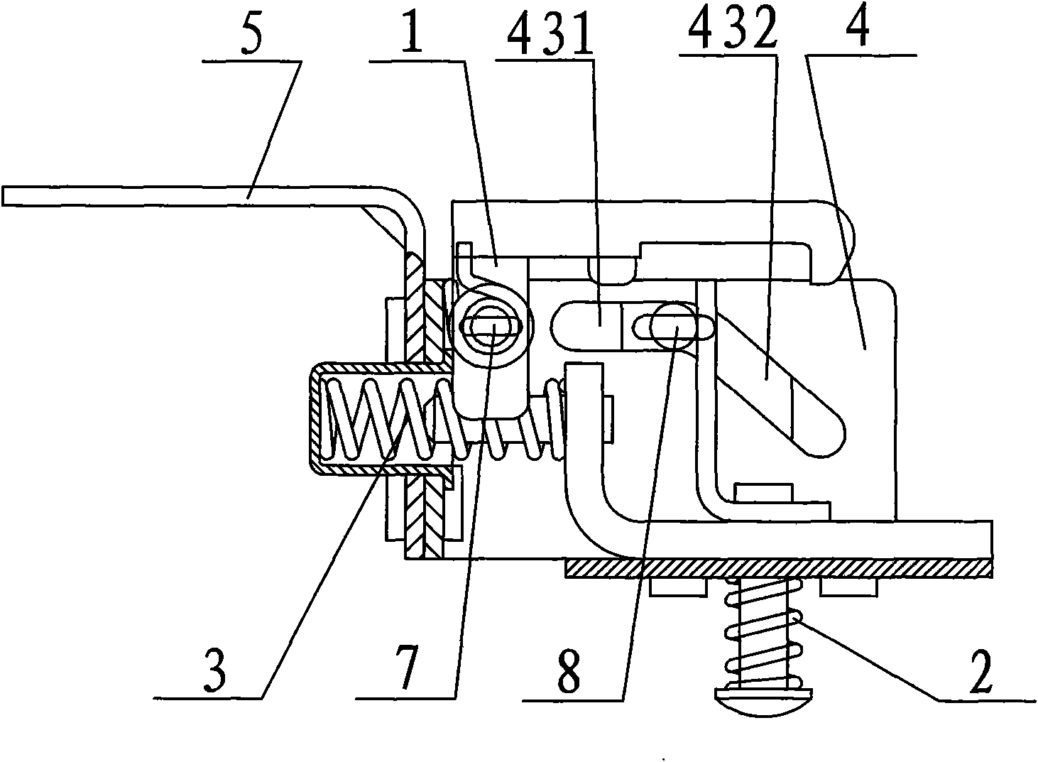
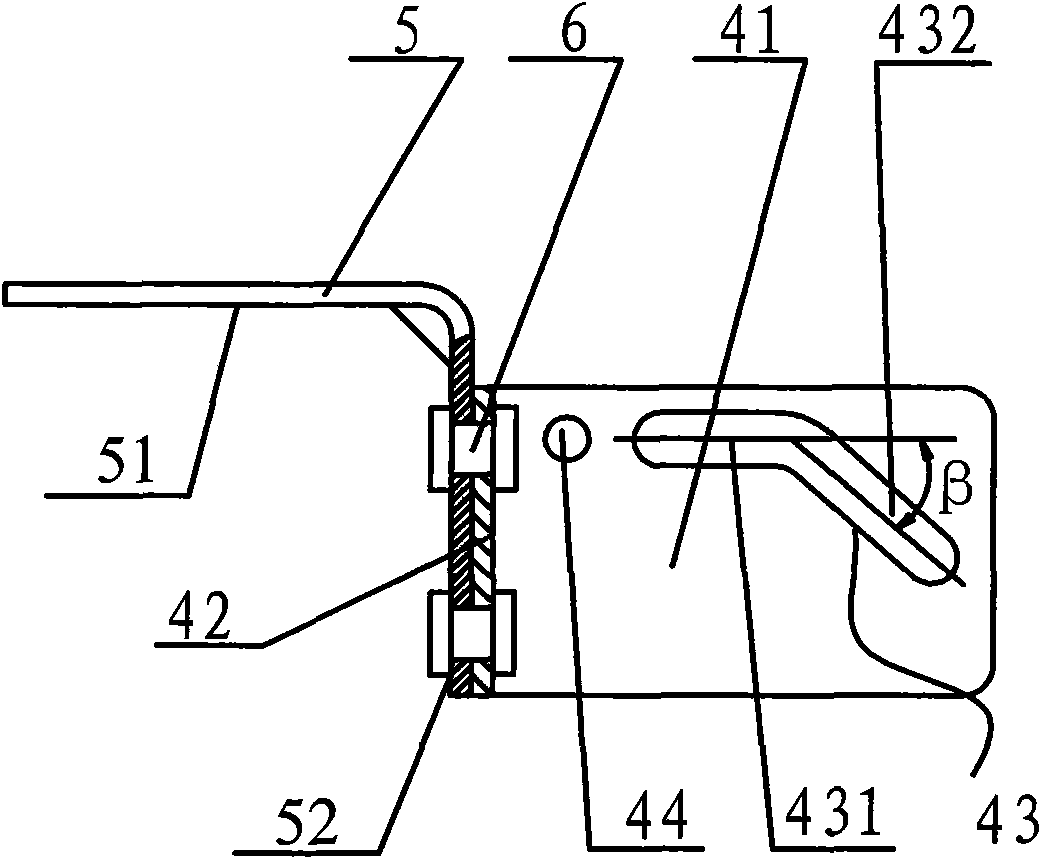
[0014] see figure 1 , the guide structure used in the opening and closing mechanism of the drop-out fuse of the present invention includes a guide rail frame 4 and a bracket 5, wherein,

[0015] The guide rail frame 4 has a pair of end plates 41 arranged parallel to the front and rear and a mounting base plate 42 vertically connected to the left end of the end plate 41. Several rivet holes are provided on the mounting base plate 42; A guide slot 43, the guide slot 43 is composed of a connected section of horizontal slot 431 and a section of oblique slot 432 that is bent downward and forms an angle with the horizontal slot 431 and is β=30°~40°; A pair of end plates 41 are respectively provided with a locking pin hole 44 at the left front of the guide slot 43;

[0016] Bracket 5 is made of a horizontal part 51 and a vertical part 52...


PUM


Abstract

The invention discloses a guide structure in the switching mechanism of a drop-out type fuse. The switching mechanism comprises a releasing device, a fastening device, a resetting device and the guide structure. The guide structure comprises a guide rail bracket and a supporting bracket, wherein the guide rail bracket has a pair of front and back end plates which are arranged in parallel and a mounting bottom plate vertically connected with the left ends of the end plates, a plurality of rivet holes are formed in the mounting plate, the pair of end plates has guide holes which are opposite, and each guide hole consists of a horizontal slot and a downward-bent oblique slot which forms an included angle beta with the horizontal slot; and the supporting bracket consists of a horizontal part and a vertical part connected with the right end of the horizontal part, the side face of the vertical part also has rivet holes corresponding to the rivet holes on the guide bracket and also has mounting holes for mounting the resetting device. The guide structure is mainly used for limiting the motion tracks of a contact seat and the resetting device.

Description

technical field [0001] The invention relates to a guide structure used in an opening and closing mechanism of a dropout fuse. Background technique [0002] Drop-out fuse is the most commonly used short-circuit protection switch for branch lines of 10kV distribution lines and distribution transformers. It is economical, easy to operate, and adaptable to outdoor environments. It is widely used in 10kV distribution lines and power distribution The primary side of the transformer is used for protection and equipment switching and switching operations. Its working principle is: put the fuse wire into the fuse tube, tighten both ends, and make the fuse wire above the middle of the fuse tube, and the upper moving contact will tilt up perpendicular to the fuse tube due to the tension of the fuse wire. The insulating pull rod pushes the upper moving contact into the upper static contact to form a closed state (closing state) and maintain this state. When the protected line fails an...

Claims


Application Information

Patent Timeline
Patent Type & Authority Applications(China)
IPC IPC(8): H01H71/20H01H85/54
Inventor 陆敏强
Owner 浙江赛菲特电气有限公司
Why Eureka
Try Eureka