Light-emitting diode packaging structure and backlight module
A technology of light-emitting diodes and structures, applied in optics, nonlinear optics, instruments, etc., can solve the problems of insufficient luminous efficiency of red light and the inability to meet the needs of a wider color gamut
Active Publication Date: 2011-01-05
SHENZHEN CHINA STAR OPTOELECTRONICS TECH CO LTD
View PDF6 Cites 38 Cited by
- Summary
- Abstract
- Description
- Claims
- Application Information
AI Technical Summary
Problems solved by technology
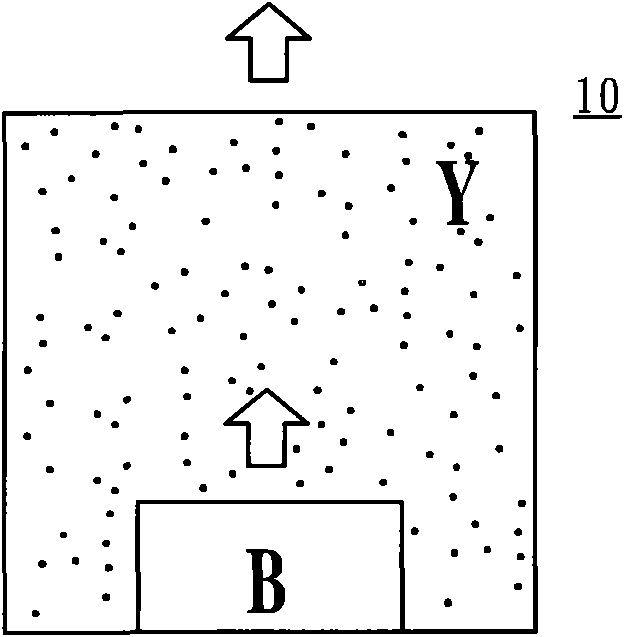
However, the disadvantage of the LED package structure 10 in FIG. 1A is that the white light produced by mixing blue light and excited yellow light can only exhibit about 70% of the color gamut, which cannot meet the demand for a wider color gamut.
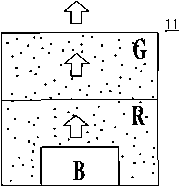
Furthermore, the disadvantage of the LED packaging structures 11 and 12 in FIGS. 1B and 1C is that part of the red light will be absorbed or scattered by the green phosphor, resulting in insufficient luminous efficiency of the red part.
Method used
View moreImage
Smart ImageViewing Examples

Examples
Embodiment Construction
Login to View More PUM
 Abstract
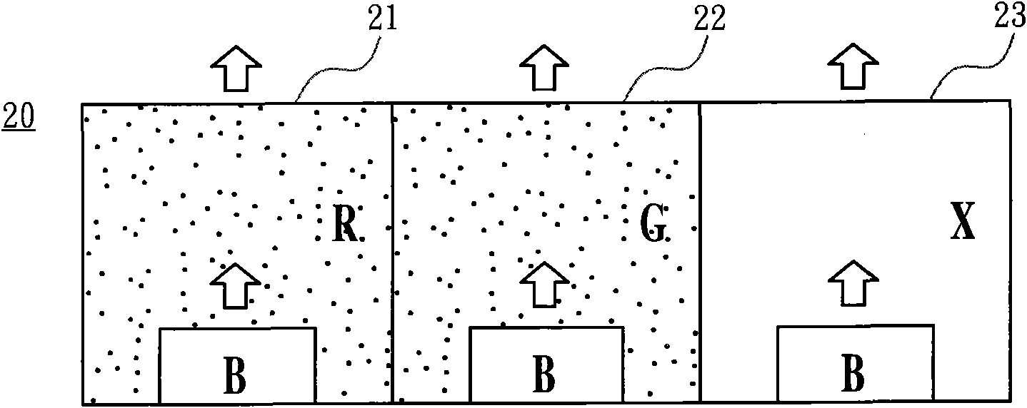
The invention discloses a light-emitting diode packaging structure and a backlight module. The light-emitting diode packaging structure is assembled in the backlight module of the liquid crystal display to be the backlight of the backlight module. The light-emitting diode packaging structure provides three independent LED packaging structures adjacent to each other, wherein the three LED packaging structures are used for respectively generating a red light, a green light and a blue light which can be mutually mixed into white light. The design can ensure that various colored lights can not be absorbed or scattered by fluorescent powder with other colors, therefore the light-emitting diode packaging structure is beneficial to regulating and controlling single colors, increasing the light-emitting efficiency of each colored light and enlarging the color gamut of the white light.
Description
Light emitting diode packaging structure and backlight module 【Technical field】 The present invention relates to a light-emitting diode packaging structure and a backlight module, in particular to a light-emitting diode packaging structure capable of monochromatic control and improving the luminous efficiency of each color light, and a backlight module with the light-emitting diode packaging structure. 【Background technique】 Liquid crystal displays (LCDs) have been widely used in various electronic products. Most of the LCDs are backlight LCDs, which are composed of a liquid crystal display panel and a backlight module. The backlight module can be divided into two types according to the incident position of the light source: side-light type and direct-light type, so as to provide backlight to the LCD panel, and the direct-light type backlight module The structured backlight source can be cold cathode fluorescent tube (coldcathodefluorescentlamp, CCFL), light emitting diode...
Claims
Login to View More Application Information
Patent Timeline
 IPC IPC(8): H01L25/13H01L33/50G02F1/13357
CPCH01L2924/0002H01L25/075H01L33/504G02F1/133603
Inventor 贺成明任杰林博瑛
Owner SHENZHEN CHINA STAR OPTOELECTRONICS TECH CO LTD
Features
- Generate Ideas
- Intellectual Property
- Life Sciences
- Materials
- Tech Scout
- Unparalleled Data Quality
- Higher Quality Content
- 60% Fewer Hallucinations
Learn More Browse by: Latest US Patents, China's latest patents, Technical Efficacy Thesaurus, Application Domain, Technology Topic, Popular Technical Reports.
© 2025 PatSnap. All rights reserved.Legal|Privacy policy|Modern Slavery Act Transparency Statement|Sitemap|About US| Contact US: help@patsnap.com