Coating machine of battery pole pieces

A battery pole piece and coating machine technology, which is applied to battery electrodes, circuits, electrical components, etc., can solve the problems of poor interchangeability, no product model replaceability, low efficiency, etc., and achieves high speed and good packaging effect. , the effect of accurate positioning

Inactive Publication Date: 2011-01-05
DONGGUAN HONBRO LI BATTERY EQUIP TECH
4 Cites 14 Cited by

AI-Extracted Technical Summary

Problems solved by technology

This method can only cover one pole piece at a time, which is inefficient; the interchangeability is poor, and it can only be coated for one specification of the pole piece, and does not have th...

Method used

Design focus of the present invention is, on the one hand, its positioning mechanism is provided with special-purpose fixture to make membrane material, pole piece location accurately; Before encapsulating, remove membrane material static electricity with ion wind and flatten it in hot-press packaging, product The packaging effect is good; on the other hand, its feeding mechanism, discharging mechanism and packaging mechanism can complete multiple pole piece operations at one time, and the materials can be collected into the trough. Thereby, the pole piece can be reliably packaged with the diaphragm, and has the advantages of simplicity, reliability, high speed, good product consistency, accurate positioning, and automatic operation.
Positioning mechanism 100 is installed on frame 10, comprises driver, turntable 101, jig, jig drive, air knife and fixed plate 110; Driver includes divider 150 and motor 151, wherein, turntable 101 and divider 150 The output shaft is connected and can be driven by the motor 151; the jigs are equiangularly distributed on it with the axis of rotation of the turntable 101 as the center, and its number is equal to the number of circumferential divisions of the divider 150; the jigs include a fixed plate 102 and a pressing plate 1...

Abstract

The invention relates to a coating machine of battery pole pieces, in particular to automatic machinery for packaging battery pole pieces with an isolating film in the manufacture process of lithium batteries. The coating machineautomatic machinery comprises a stand, a positioning mechanism, a feeding mechanism, a filming mechanism, a sealing mechanism and a discharging mechanism, wherein the positioning mechanism adopts a multi-station stepping mode is adopted for the positioning mechanism, and jigstools are circumferentially arranged for positioning film materials and pole pieces. The pole pieces are put in the jigstools from the feeding mechanism, automatically folded and packaged withby film materials, sealed into bags by the sealing mechanism and collected by the discharging mechanism to be put into a feeding groove. The invention has the advantages of simple and reliable structure, high productivityenergy yield, accurate positioning, consistenttant products and operation automation.

Application Domain

Technology Topic

Image

  • Coating machine of battery pole pieces
  • Coating machine of battery pole pieces
  • Coating machine of battery pole pieces

Examples

  • Experimental program(1)

Example Embodiment

[0037] The present invention will be further described below in conjunction with the drawings.
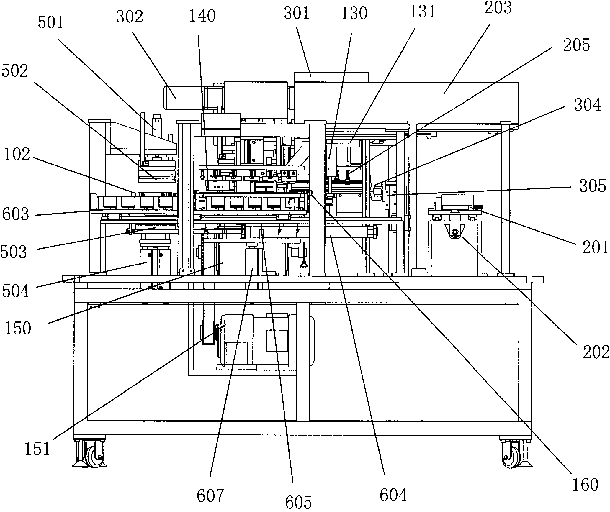
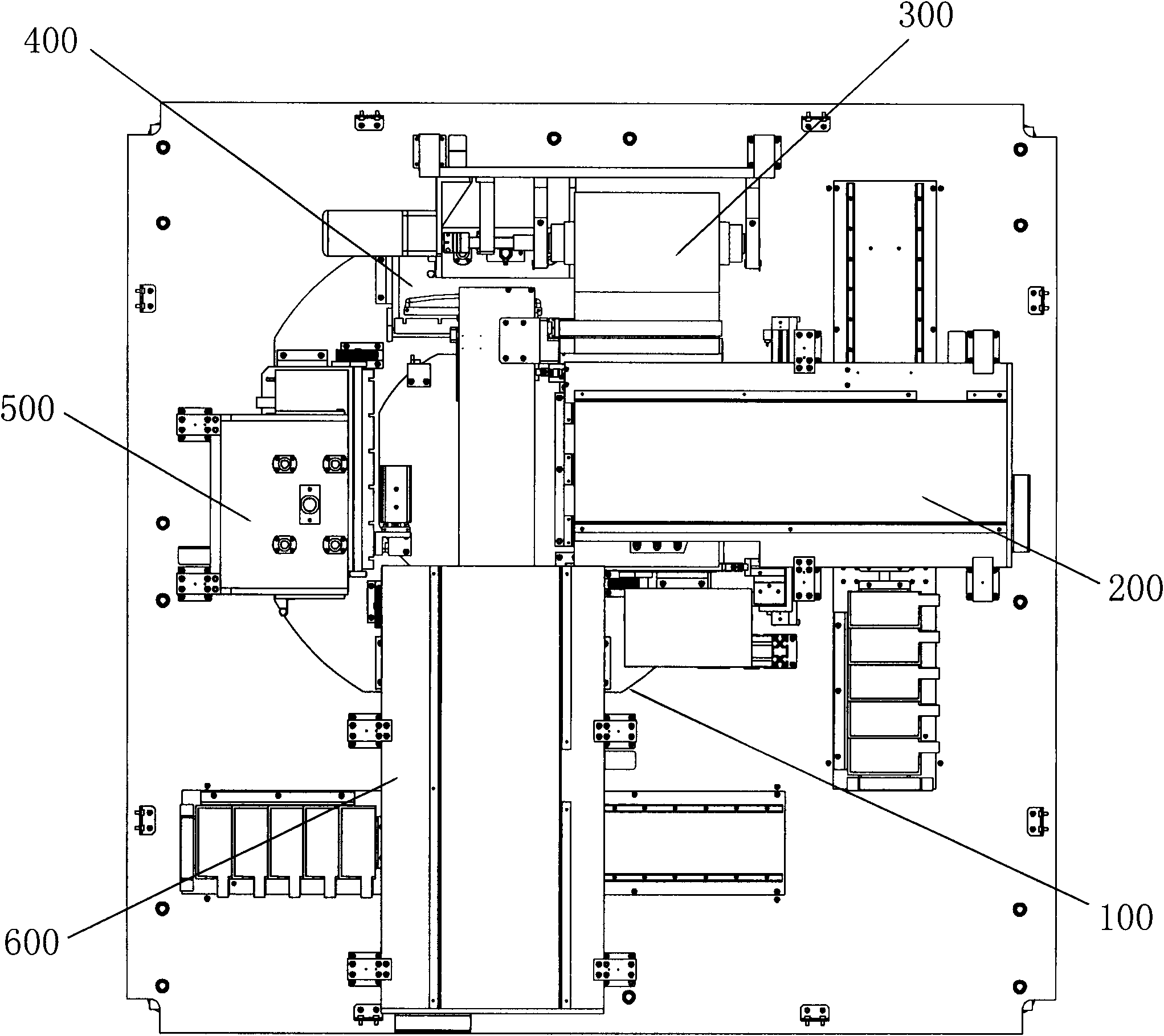
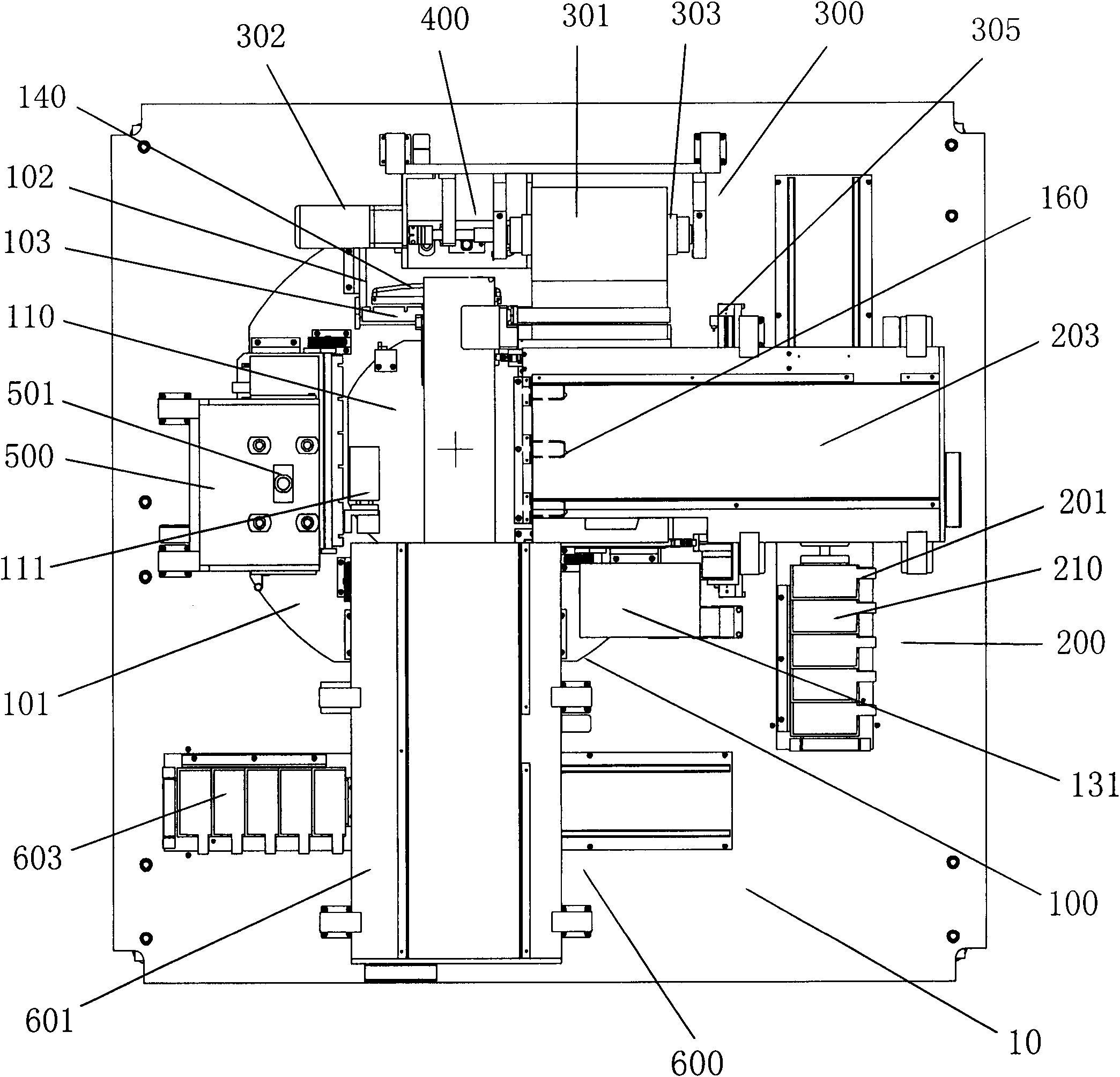
[0038] First, please refer to figure 1 , figure 2 , image 3 , Figure 4 and Figure 5 , Which shows the specific structure of the preferred embodiment of the present invention.
[0039] figure 1 , figure 2 , image 3 , Figure 4 and Figure 5 The battery pole piece coating machine shown includes a frame 10, a positioning mechanism 100, a feeding mechanism 200, a laminating mechanism 300, a first sealing mechanism 400, a second sealing mechanism 500, and a discharging mechanism 600; the positioning mechanism 100 adopts The multi-station stepping method of the feeding station, the heat-sealing station and the discharging station, on which the clamp positioning pole piece is arranged, and the station is changed intermittently; the feeding mechanism 200 is set at the feeding station of the positioning mechanism 100 On the side of the position, the manipulator holds the pole piece in the trough and puts it on the fixture of the positioning mechanism 100; the laminating mechanism 300 is set above the pole piece feeding station, and the isolation film is fixed-length; the sealing mechanism is set at the positioning The heat-sealing station of the mechanism 100 heats and bonds the diaphragm to position and wrap the internal battery pole pieces; the discharging mechanism 600 is arranged on the side of the discharging station of the positioning mechanism 100, and the packaged packaging bag is divided into The monomer is vacuum sucked by the manipulator and put it into the receiving tank.
[0040] The positioning mechanism 100 is installed in the frame 10 and includes a driver, a turntable 101, a fixture, a fixture drive, an air knife, and a fixed plate 110; the driver includes a splitter 150 and a motor 151, among which the turntable 101 and the output shaft of the splitter 150 It is connected and can be driven by a motor 151; the fixtures are distributed on the rotating axis of the turntable 101 at equal angles, and the number is equal to the number of divisions in the circumference of the divider 150; the fixture includes a fixed plate 102 and a pressure plate 103, a fixed plate 102 and a pressure plate 103 is connected by hinge 104, fixed plate 102 is fixed on turntable 101; the fixture drive includes A cylinder 111, B cylinder 130 and C cylinder 131. The vertical B cylinder 130 and the horizontal C cylinder 131 are connected to form a closed drive, corresponding to The feeding mechanism 200 is installed on the fixed plate 110 to drive the pressing plate 103 to turn and close; the A cylinder 111 is installed on the fixed plate 110 corresponding to the discharging mechanism to open the pressing plate 103; the air knife includes A nozzle 140 and B nozzle 160 , B tuyere 160 is installed on the fixed plate 110 corresponding to the feeding mechanism. When the pressing plate 103 is closed, the ion wind is blown out to the diaphragm 301 in a controlled manner, so that it turns with the pressing plate 103 to enclose the pole piece 210 on the fixture; D cylinder 141 and E cylinder, D cylinder 141, E cylinder 142 are respectively connected with A nozzle 140, corresponding to the installation of the first sealing mechanism 400, A nozzle 140 moves vertically and horizontally, blows out ion wind to flatten the diaphragm 301 The pole piece 210 is attached to facilitate sealing.
[0041] The position of the feeding mechanism 200 shown corresponds to the feeding station setting of the positioning mechanism 100, and includes a storage tank 201, a positioner 202, a manipulator 203, and a suction cup 205. The pole piece 210 is stored in the storage tank 201, The plurality of storage tanks 201 are divided into two groups, which are switched by the indexer 202, and the A suction cup 205 sucks the pole piece 210 into the fixed plate 102 of the fixture.
[0042] The position of the laminating mechanism 300 shown corresponds to the feeding station of the positioning mechanism 100 next to the heat-sealing station, including the B motor 302, the reel 303, the gripper 304, the driver 305, and the film material 301. The driver 305 drives the gripper. 304 clamps the film material 301, sends the diaphragm into the fixed plate 102 of the aforementioned jig, and cuts the film material after placing the pole piece 210.
[0043] The sealing mechanism shown includes a first sealing mechanism 400 and a second sealing mechanism 500, which are respectively arranged at the top sealing station and the side sealing station of the heat sealing station, that is, the top edge and the side edge of the heat-press packaging diaphragm, Make it wrap the pole piece. The first sealing mechanism 400 is installed on the frame 10 and includes a seal A 401 and an F cylinder 402. The A seal 401 is aligned with one side of the package, and the built-in electric heating tube controls the temperature. The F cylinder 402 drives the hot pressing film 301 to Glue one side. The second sealing mechanism 500 shown is installed on the frame 10 and includes a G cylinder 501, an upper seal 502, a lower seal 503, and an H cylinder 504. The upper seal 502 has a built-in electric heating tube to control the temperature and is connected to the G cylinder 501. The lower seal 503 and The H cylinder 504 is connected, and the two are aligned up and down on the other side of the package. The G cylinder 501 and the H cylinder 504 drive both sides of the hot-pressing adhesive film 301.
[0044] The discharging mechanism 600 shown is installed on the side of the turntable 101 of the frame 10, and its position corresponds to the discharging station of the positioning mechanism 100. It includes a B robot 601, a B suction cup 602, a trough 603, a J cylinder 604, a cutter 605, The K cylinder 607 is connected to the cutter 605 to divide the multiple sealed packaging bags into a single section. The B suction cup 602 puts each packaged product into the trough 603.
[0045] The key point of the design of the present invention is that, on the one hand, the positioning mechanism is equipped with a special fixture to accurately position the film material and pole piece; ion wind is used to remove the static electricity of the film material before packaging and flatten it in the hot-press packaging, and the product packaging effect is good. ; On the other hand, its feeding mechanism, discharging mechanism and packaging mechanism can complete multiple pole piece operations at one time and collect materials into the trough. In this way, the pole piece can be packaged with a diaphragm reliably, which has the advantages of simplicity, reliability, high speed, good product consistency, accurate positioning, and automatic operation.
[0046] The above are only the preferred embodiments of the present invention and do not limit the technical scope of the present invention. Therefore, any minor modifications, equivalent changes and modifications made to the above embodiments based on the technical essence of the present invention belong to The protection scope of the technical solution of the present invention.

PUM

no PUM

Description & Claims & Application Information

We can also present the details of the Description, Claims and Application information to help users get a comprehensive understanding of the technical details of the patent, such as background art, summary of invention, brief description of drawings, description of embodiments, and other original content. On the other hand, users can also determine the specific scope of protection of the technology through the list of claims; as well as understand the changes in the life cycle of the technology with the presentation of the patent timeline. Login to view more.

Similar technology patents

Targeted advertising by context of media content

InactiveUS20110179445A1Precise positioningWeight increaseElectronic editing digitised analogue information signalsUsing detectable carrier informationTargeted advertisingMedia content
Owner:TELEFON AB LM ERICSSON (PUBL)

Portable stand-alone device, particularly suitable for use in surgery, micro-component handling and the like

ActiveUS20140371761A1Minimal hand movementPrecise positioningMicromanipulatorDiagnosticsRotational degrees of freedomActuator
Owner:JUANPERA JESUS HERNANDEZ

Vehicle seat

Owner:TOYOTA BOSHOKU KK

Classification and recommendation of technical efficacy words

  • Good packaging
  • Precise positioning

Method for producing two-way stretching polypropylene film for cigarette by pipe soaking method

InactiveCN1425549AHigh heat shrinkageGood packagingPolypropyleneSmall footprint
Owner:海南日新酒店管理有限公司

Double-twist packing machine

ActiveCN103213700AGood packagingImprove aestheticsWrapper folding/bending apparatusWrappingPaper sheetDISC assembly
Owner:成都三可实业有限公司

Coin arranging packager

InactiveCN105819026AEfficient packaging processGood packagingPackagingEnergy consumptionPulp and paper industry
Owner:GUANGXI UNIVERSITY OF TECHNOLOGY

Motor rotor automatic packaging and paper cutting device for motor rotor

InactiveCN106800102AImprove packaging efficiencyGood packagingWrapping material feeding apparatusWeb rotation wrappingPaper cutSpray nozzle
Owner:HUZHOU YOUCHUANG TECH CO LTD

Double-end-sealing reciprocating high-speed pillow-type packing machine

PendingCN109693838AStrong and reliable sealingGood packagingWrapper twisting/gatheringSphere packingMechanical engineering
Owner:瑞安市海创机械有限公司

Method and device for accurately positioning a patient in radiotherapy and/or radiosurgery

InactiveUS6865253B2Precise positioningGood flexibilityForeign body detectionRadiation beam directing meansX ray imageSoft x ray
Owner:BRAINLAB

Heart Valve Stent

InactiveUS20120283824A1Precise positioningSecure fixationSuture equipmentsStentsHeart chamberHeart valve stenosis
Owner:LUTTER GEORG +1
Why Eureka
Try Eureka