Feeding structure for stone cutter

A technology of stone cutting machine and feeding mechanism, which is applied in the direction of stone processing tools, stone processing equipment, work accessories, etc., can solve the problem that the rock cannot be prevented from shaking up and down, and achieve the effect of adding blocks and cutting, and the speed is stable and slow

Inactive Publication Date: 2011-01-12
佛山市顺德区悍天睿数控机械有限公司
View PDF7 Cites 9 Cited by
  • Summary
  • Abstract
  • Description
  • Claims
  • Application Information

AI Technical Summary

Problems solved by technology

This structure can prevent the stone being processed from moving lef

Method used


Image

  • Feeding structure for stone cutter
  • Feeding structure for stone cutter
  • Feeding structure for stone cutter

Examples


no. 1 example

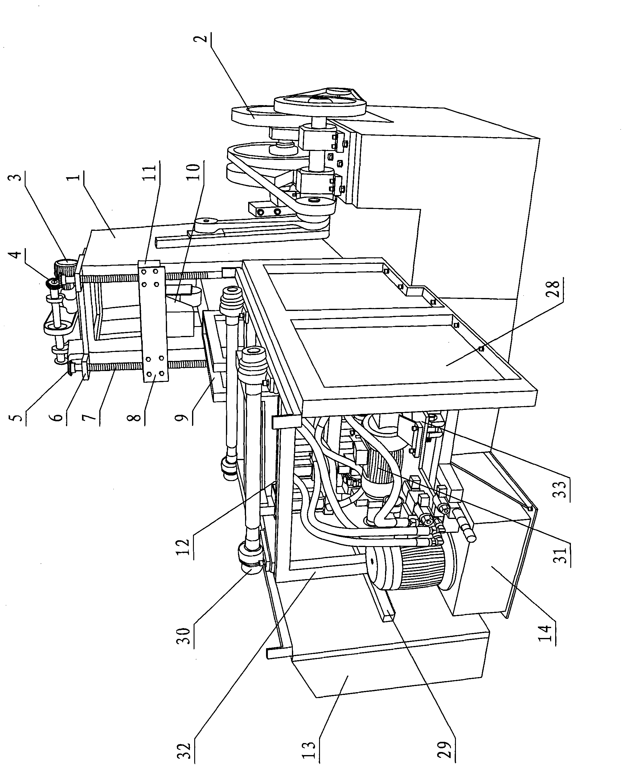
[0034] see figure 1 , Figure 11-Figure 13 , the feeding structure of the stone cutter includes a feeding mechanism 12 arranged at the rear of the frame 1 and capable of moving back and forth, a receiving part 21 for placing stones is arranged in front of the feeding mechanism, a cutting part is arranged in front of the receiving part, and a cutting part Connected with the main drive mechanism 2, the rear of the frame is provided with a rack 29 transversely, and the feeding mechanism is provided with a forward gear 40 driven by a forward motor 44 and a reverse gear 39 driven by a reverse motor 31. The forward gear and the reverse gear are respectively It is connected with the front lifting mechanism and the rear lifting mechanism, so that the forward and backward gears are engaged with or disengaged from the rack through the lifting movement.

[0035] The left and right sides of the rear portion of the frame 1 corresponding to the feeding mechanism 12 are provided with fixed ...

no. 2 example

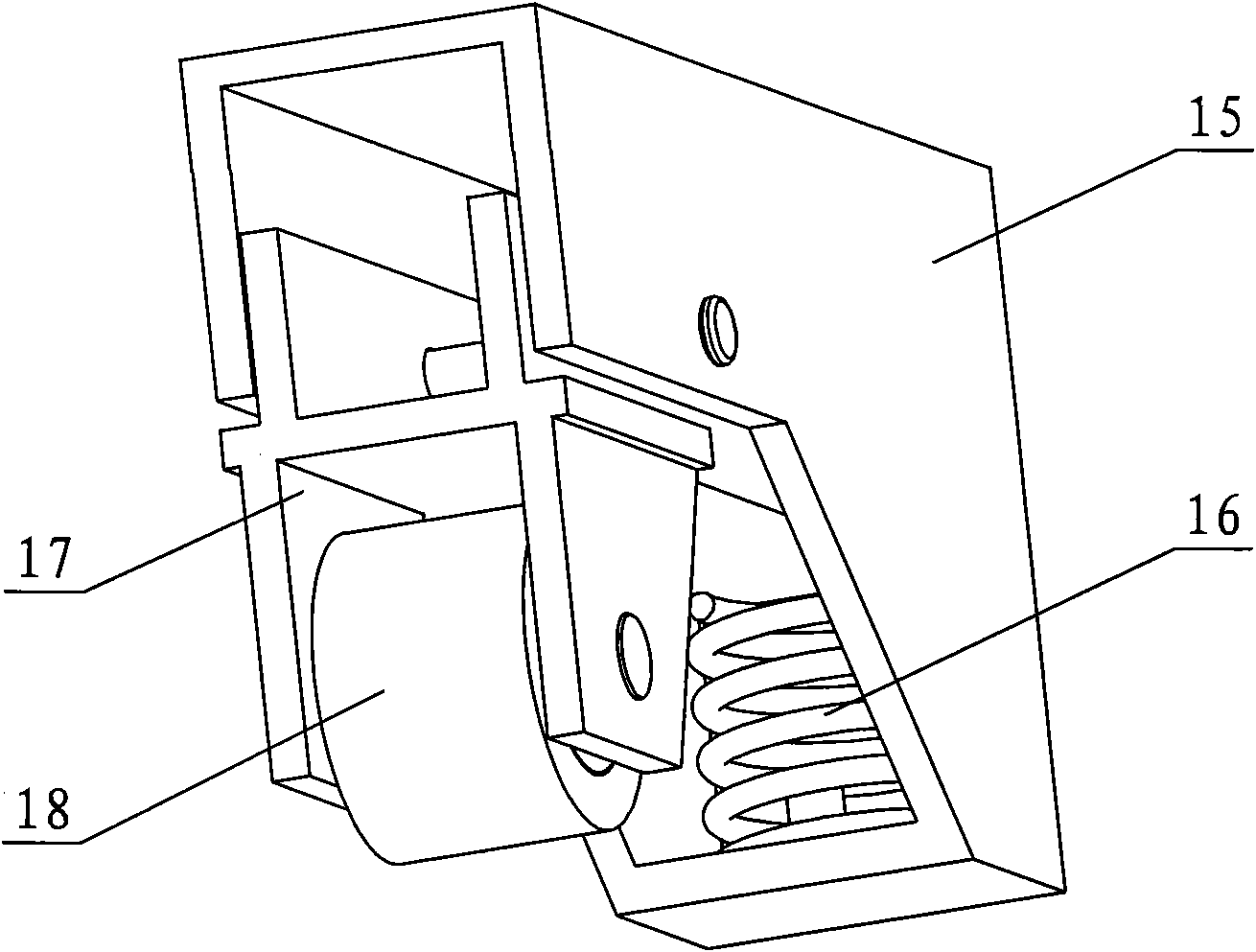
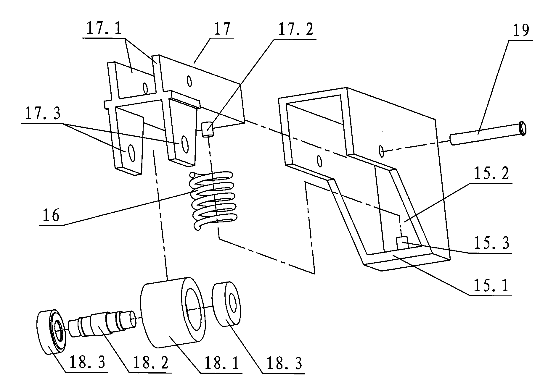
[0048] see Figure 7 , the top surface of the movable seat 17' is provided with hinged ears hinged with the fixed seat 15' at least in the middle front, and the front end of the bottom surface is provided with a roller shaft seat connected with the pressing roller 18; the fixed seat is connected with the frame through a lifting mechanism, and the upper part is provided with There is a fixed seat top plate 15.4'; the elastic member is a tension spring 16', and the upper and lower ends are connected with the fixed seat top plate 15.4' and the rear end top surface of the movable seat respectively. Other unmentioned parts are the same as the first embodiment.


PUM


Abstract

The invention relates to a feeding structure for a stone cutter, which comprises a feeding mechanism, wherein the feeding mechanism is arranged at the rear part of the machine frame and can move back and forth; a bearing part for placing stones is arranged in front of the feeding mechanism; a blanking part is arranged in front of the bearing part; the blanking part is connected with a main driving mechanism in a transmission mode; the rear part of the machine frame is transversely provided with a rack; the feeding mechanism is provided with a forward gear and a backward gear, the forward gear is driven by a forward motor, and the backward gear is driven by a backward motor; and the forward gear and the backward gear are respectively connected with a front lifting mechanism and a rear lifting mechanism, so that the forward gear and the backward gear meshes with or disengage from the rack through the lifting motion. The forward and backward motions of the feeding mechanism in the invention are respectively controlled by the forward motor and the backward motor, so that the forward and backward motions of the feeding mechanism have two different speeds. Meanwhile, the forward gear and the backward gear respectively mesh with the rack fixed on the machine frame, so the forward and backward motions do not interfere with each other. The invention has the advantages of simple and reasonable structure, low cost and smooth operation, and the feeding mechanism has the advantages of high thrust force and fast backward speed.

Description

technical field [0001] The invention relates to a stone cutter, in particular to a stone cutter feeding structure. Background technique [0002] I disclosed a feeding mechanism of a stone cutter on February 4, 2004 in Chinese Patent Document No. CN2601810, which includes a feeding table and a feeding motor arranged in the feeding table. Each nut is matched with a screw rod with an external thread, and one end of the screw rod is provided with a push shovel, the bottom of the push shovel is provided with a roller, and both sides of the push shovel are respectively provided with a splint. The structure has a slow retreat speed and low production efficiency, and needs to be further improved. [0003] I disclosed a stone clamping mechanism of a stone cutter on February 4, 2004 in Chinese Patent Document No. CN2601811. It includes a vertical body, and at least one guide rail is respectively arranged on the inner walls of both sides of the vertical body along the moving direction...

Claims


Application Information

Patent Timeline
IPC IPC(8): B28D7/00B28D1/22
Inventor 周金生
Owner 佛山市顺德区悍天睿数控机械有限公司
Why Eureka
Try Eureka