Drag reducing cover body installed on tail of coach body of van or container cargo truck

A van and container technology, which is applied to vehicle parts, body, streamlined body, etc., can solve the problem of inability to reduce the resistance of the rear of the van or container freight truck, so as to reduce energy dissipation, reduce area, Reduce the effect of turbulent separation zones

Inactive Publication Date: 2011-01-12
HARBIN INST OF TECH
View PDF4 Cites 9 Cited by
  • Summary
  • Abstract
  • Description
  • Claims
  • Application Information

AI Technical Summary

Problems solved by technology

[0004] The purpose of the present invention is to provide a drag reducing cover installed at the tail of the van or container freight truck box to solve the problem of installing a wind deflector drag reducing device on the upper part of the van or container freight truck cab. Reducing the positive pressure area generated by the impact of the airflow on the protruding part of the carriage cannot reduce the rear resistance of the van or container freight truck

Method used


Image

  • Drag reducing cover body installed on tail of coach body of van or container cargo truck
  • Drag reducing cover body installed on tail of coach body of van or container cargo truck
  • Drag reducing cover body installed on tail of coach body of van or container cargo truck

Examples


specific Embodiment approach 1

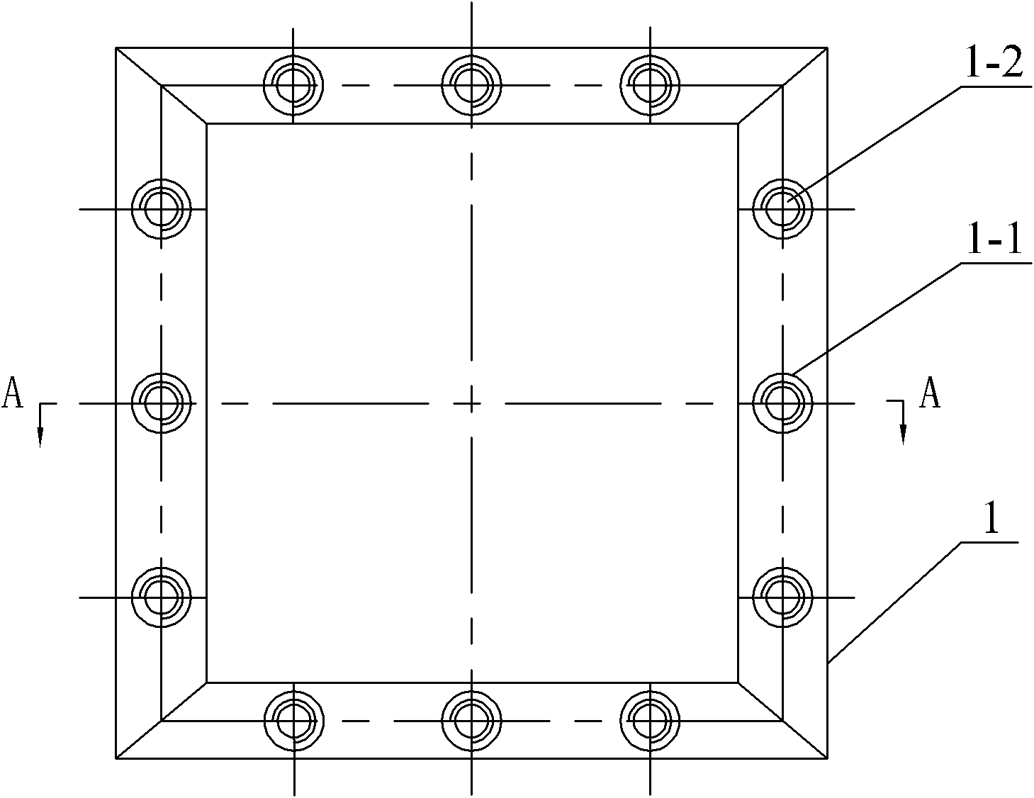
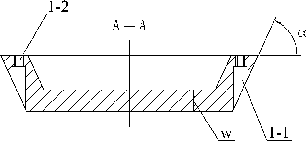
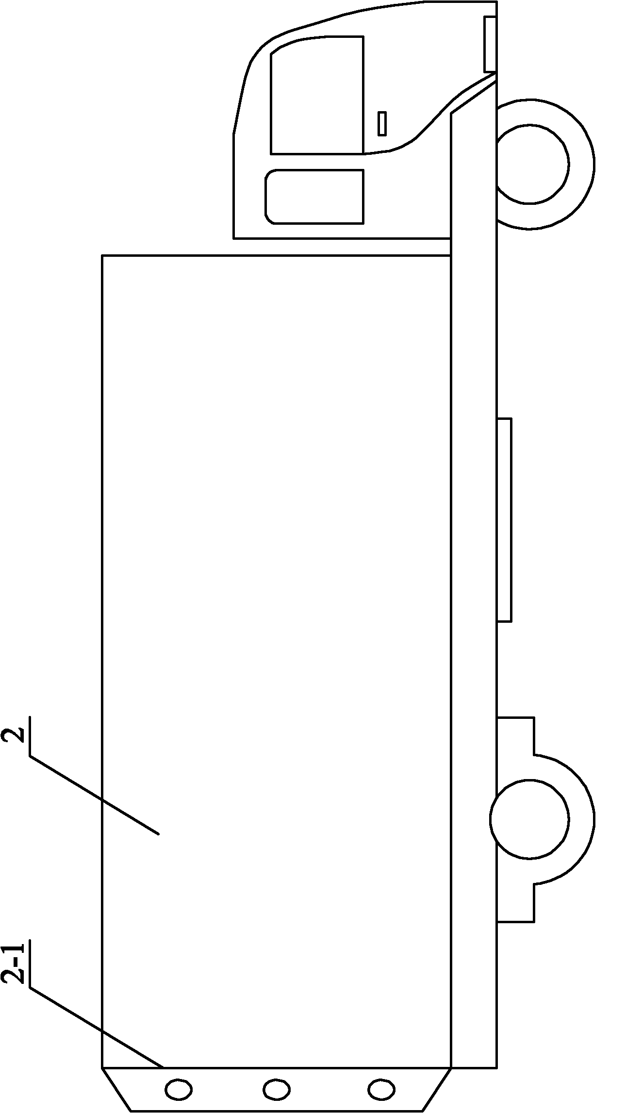
[0008] Specific implementation mode one: combine Figure 1-Figure 4 Description, the external shape of the drag reducing cover 1 described in the present embodiment is a quadrangular truss, the wall thickness w of the quadrangular truss drag reducing cover is 5mm-10mm, the inclined surface of the quadrangular truss drag reducing cover and the quadrangular truss reducing The included angle α between the large end surfaces of the resistance cover body is 50°-80°, and the large end surface of the four-sided platform drag reduction cover body is attached to the rear end surface 2-1 of the box body of the van or container freight truck 2, The four-sided platform drag-reducing cover is detachably connected to the box body tail end surface 2-1 of the van or container freight truck 2.

specific Embodiment approach 2

[0009] Specific implementation mode two: combination image 3 and Figure 4 It is illustrated that the outer periphery of the large end surface of the quadrangular truss drag-reducing cover in this embodiment coincides with the outer periphery of the rear end surface 2 - 1 of the box body of the van or container freight truck 2 . Such an arrangement can effectively reduce the turbulent flow separation zone of the airflow at the tail of the box body of the van or container freight truck, and reduce the area of ​​the negative pressure zone. Others are the same as in the first embodiment.

specific Embodiment approach 3

[0010] Specific implementation mode three: combination figure 2 Note that the wall thickness w of the quadrangular truss drag-reducing cover in this embodiment is 6 mm. Such setting can ensure the strength of the four-prism drag-reducing cover. Others are the same as in the first or second embodiment.


PUM


Abstract

The invention relates to a drag reducing cover body installed on the tail of a coach body of a van or a container cargo truck, which is installed on the van or the container cargo truck for solving the problem that the drag of the tail of a coach cannot be reduced when a dome drag reducing device is installed above a cab of the van or the container cargo truck. The shape of the drag reducing cover body is a rectangular table; the wall thickness of the rectangular table type drag reducing cover body is 5mm to 10mm; an included angle between the inclined plane and the large end surface of the rectangular table type drag reducing cover body is 50 DEG to 80 DEG; the large end surface of the rectangular table type drag reducing cover body is abutted against the end surface of the tail of the coach body of the van or the container cargo truck; and the rectangular table type drag reducing cover body is connected with the end surface of the tail of the coach body of the van or the container cargo truck in a detachable mode. The drag reducing cover body is installed on the tail of the coach body of the van or the container cargo truck and is used for reducing the pressure drag of the van or the container cargo truck in running.

Description

technical field [0001] The invention relates to a drag reducing cover installed on a van or a container freight truck. Background technique [0002] At present, the freight volume of my country's road transport has accounted for more than 70% of the comprehensive transport system. According to research, when the vehicle speed v=80km / h, the aerodynamic resistance suffered by freight cars accounts for 50% of the total resistance; for large freight cars over 8 tons, when the aerodynamic drag coefficient is reduced by 30%, the fuel consumption can be reduced by 12%. 13%. Therefore, it is of great significance to study the drag reduction of large freight vehicles. [0003] At present, in order to reduce the aerodynamic resistance of the van or container freight truck during driving, a wind deflector drag reduction device is installed on the upper part of the van or container freight truck cab. A cylindrical shape. Because the main source of resistance of the van or container ...

Claims


Application Information

Patent Timeline
Patent Type & Authority Applications(China)
IPC IPC(8): B62D35/00
Inventor 李凤臣郑智颖徐鸿鹏白哲蔡伟华
Owner HARBIN INST OF TECH
Why Eureka
Try Eureka