Rotating electrical machine
A technology of rotating motors and rotors, which is applied in the field of rotating motors and can solve problems such as shortening the life of the belt and belt slippage
- Summary
- Abstract
- Description
- Claims
- Application Information
AI Technical Summary
Problems solved by technology
Method used
Image

Examples
Embodiment approach 1
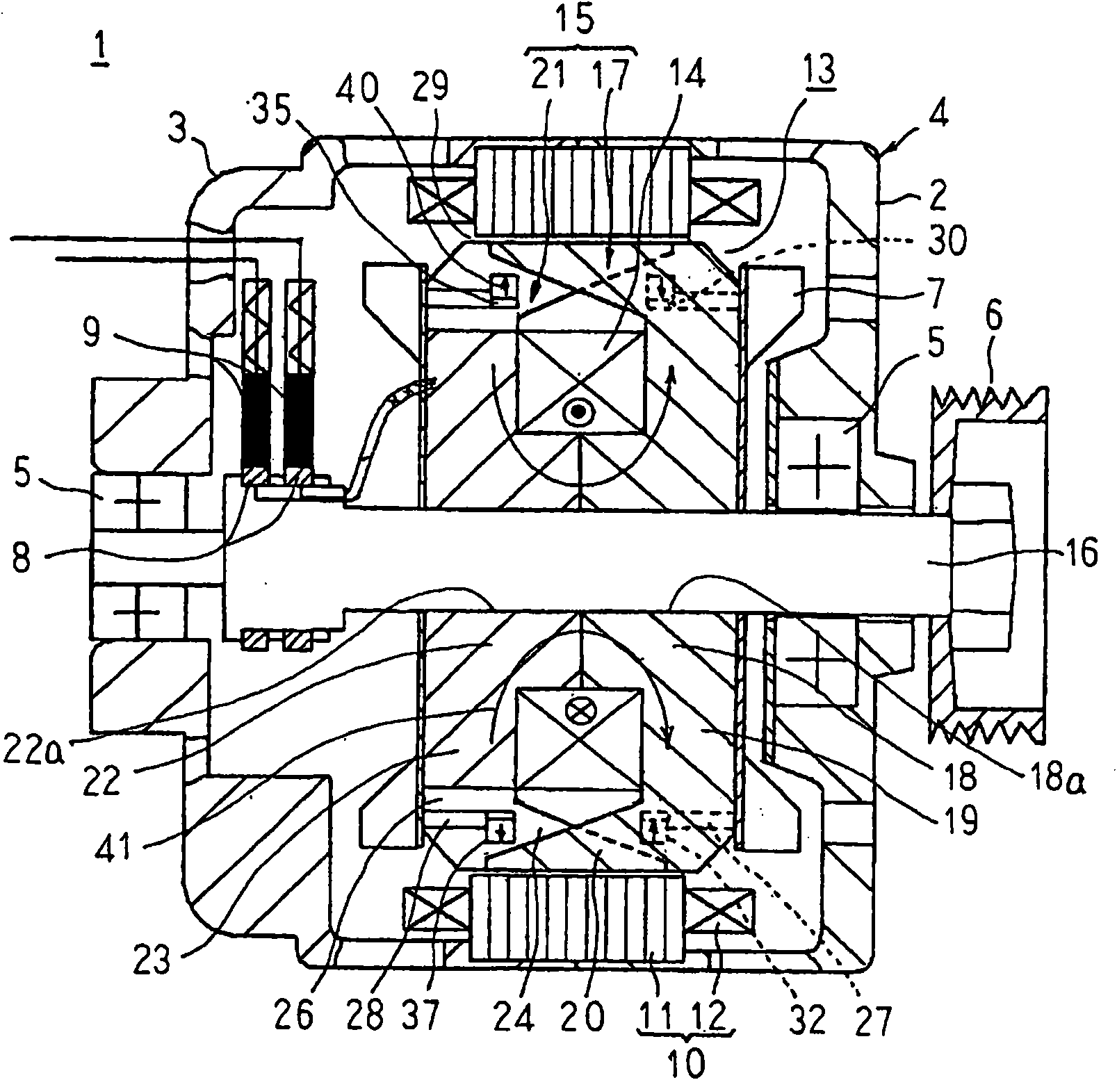
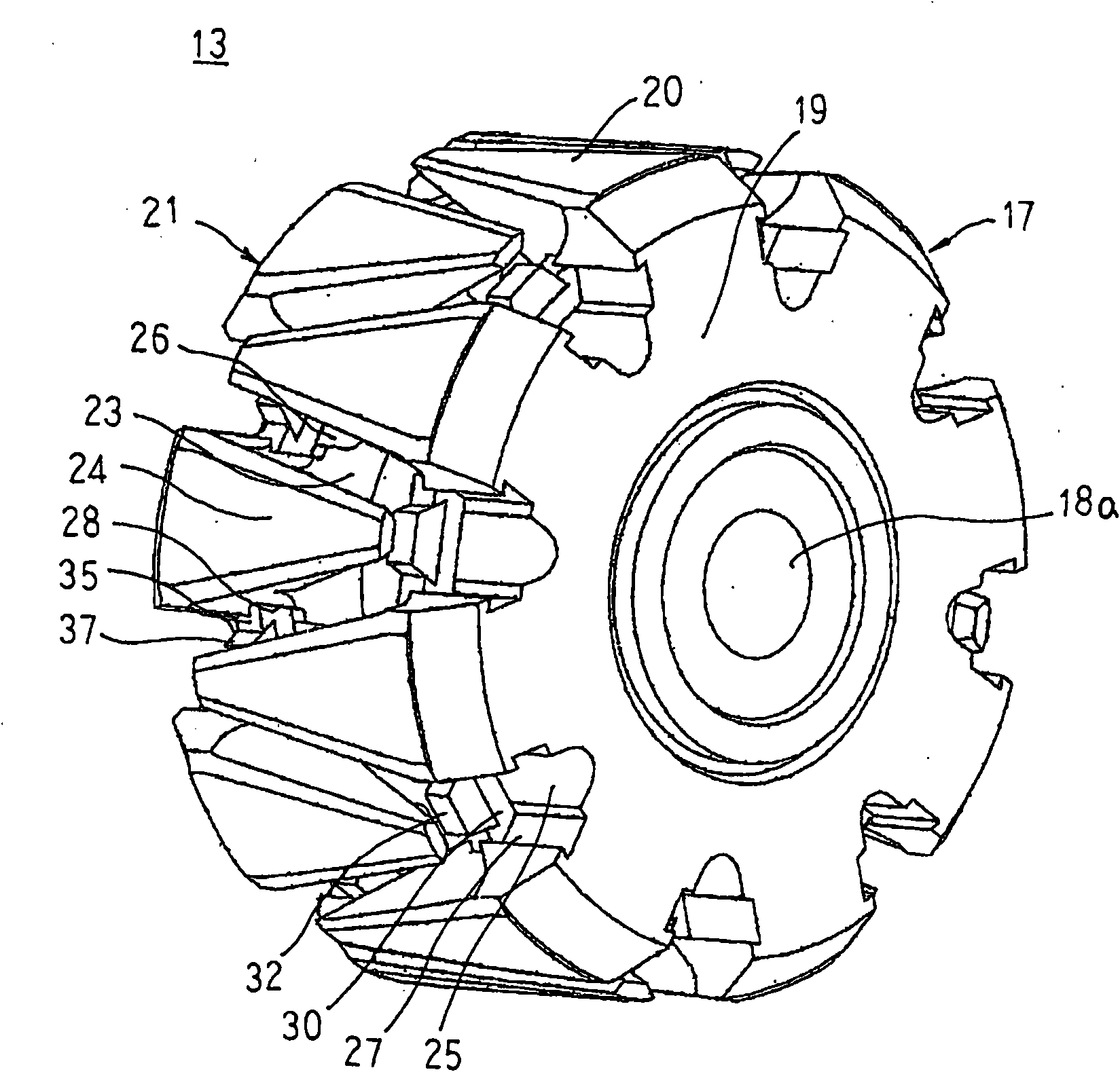
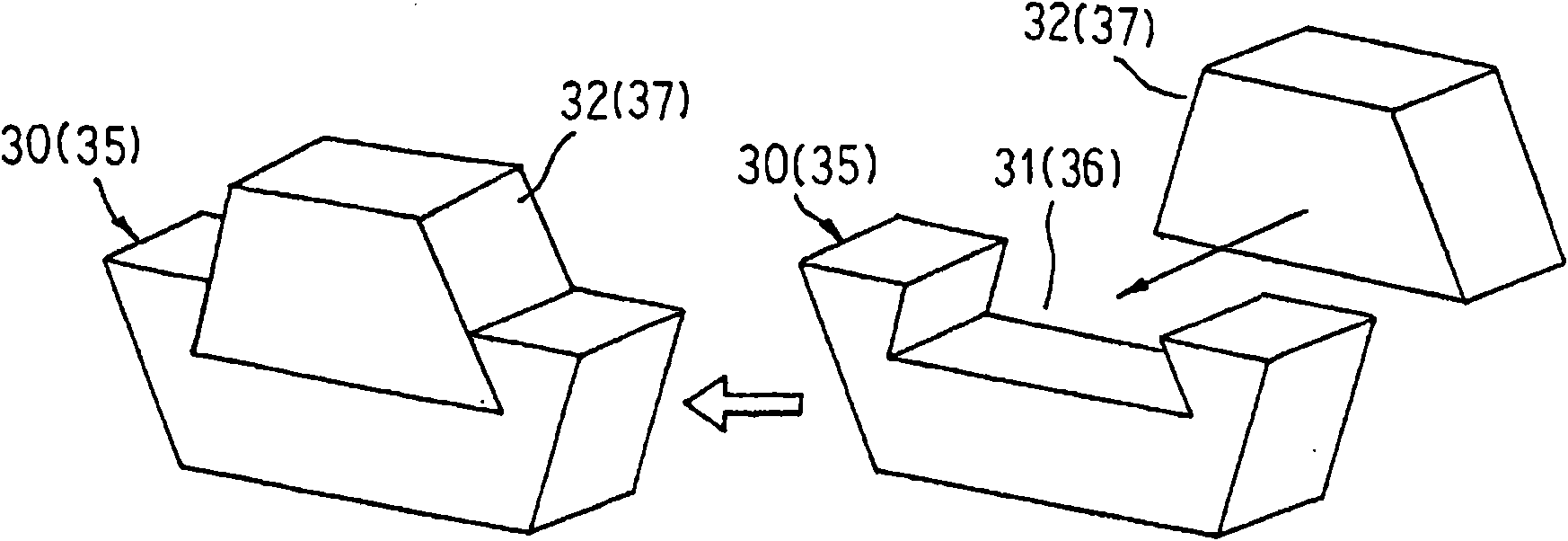
[0046] figure 1 is a cross-sectional view schematically showing the vehicle alternator according to Embodiment 1 of the present invention, figure 2 is a perspective view showing a rotor applied to the vehicle alternator according to Embodiment 1 of the present invention, image 3It is a perspective view illustrating a method of encapsulating a permanent magnet in a magnetic induction component in the vehicle alternator according to Embodiment 1 of the present invention.
[0047] Figure 1 to Figure 3 Among them, the vehicle alternator 1 includes: a housing 4 composed of a roughly bowl-shaped aluminum front bracket 2 and a rear bracket 3, a rotating shaft 16 is supported on the housing 4 via a bearing 5, and The rotor 13 rotatably arranged in the housing 4, the pulley 6 fastened to the end of the rotating shaft 16 extending to the front side of the housing 4, and the rotor 13 fixed in the axial direction (hereinafter referred to as the axial direction) The fan 7 on both end...
Embodiment approach 2
[0087] Figure 10 is a cross-sectional view showing main parts of a rotor applied to a vehicle alternator according to Embodiment 2 of the present invention, Figure 11 It is a perspective view illustrating a method of encapsulating a permanent magnet in a magnetic induction component in the vehicle alternator according to Embodiment 2 of the present invention.
[0088] Figure 10 as well as Figure 11 Among them, the first permanent magnet 32A is formed as a flat surface whose upper surface is substantially parallel to the inner peripheral surface on the front end side of the second claw-shaped magnetic pole portion 24 . Therefore, the magnetization direction 40 of the first permanent magnet 32A is a direction perpendicular to the upper surface thereof. Here, the second permanent magnet has the same configuration as the first permanent magnet 32A.
[0089] In addition, other configurations are configured in the same manner as in the first embodiment described above.
[0...
Embodiment approach 3
[0094] Figure 12 is a cross-sectional view showing main parts of a rotor applied to a vehicle alternator according to Embodiment 3 of the present invention, Figure 13 It is a perspective view illustrating a method of encapsulating a permanent magnet in a magnetic induction component in the vehicle alternator according to Embodiment 3 of the present invention.
[0095] Figure 12 as well as Figure 13 In the first magnetic induction member 30A, the bottom surface of the first fitting groove 31A is formed as a flat surface substantially parallel to the inner peripheral surface on the front end side of the second claw-shaped magnetic pole portion 24 . Here, the second magnet holding portion has the same configuration as the first magnetic induction member 30A.
[0096] In addition, other configurations are configured in the same manner as in the first embodiment described above.
[0097] In the rotor 13B thus constituted, since the first magnetic induction member 30A is fit...
PUM
 Abstract
Description
Claims
Application Information
 - R&D
- Intellectual Property
- Life Sciences
- Materials
- Tech Scout
- Unparalleled Data Quality
- Higher Quality Content
- 60% Fewer Hallucinations
Browse by: Latest US Patents, China's latest patents, Technical Efficacy Thesaurus, Application Domain, Technology Topic, Popular Technical Reports.
© 2025 PatSnap. All rights reserved.Legal|Privacy policy|Modern Slavery Act Transparency Statement|Sitemap|About US| Contact US: help@patsnap.com