Flame arrester

A flame remover and flame technology, applied in the direction of burners, fire rescue, gas fuel burners, etc., can solve the problems that it is difficult to meet the required manufacturing accuracy, increase the pressure loss of combustible gas, etc., and achieve easy disassembly and reinstallation, friction Less pressure loss, elimination of deflagration and explosion effects

Inactive Publication Date: 2011-01-19
KANEKO SANGYO CO LTD
View PDF1 Cites 1 Cited by
  • Summary
  • Abstract
  • Description
  • Claims
  • Application Information

AI Technical Summary

Problems solved by technology

The greater width of the scavenger increases the pressure loss of the combustible gas flowing through the gap
[0006] In addition, it is difficult for the traditional flame arrester to have small gaps to allow the flow of combustible gas and prevent the intrusion of external flames to eliminate deflagration and explosion
This conventional flame arrester is also difficult to achieve the required manufacturing precision, thus causing disadvantages in forming and assembling

Method used


Image

  • Flame arrester
  • Flame arrester
  • Flame arrester

Examples


Embodiment Construction

[0016] A preferred embodiment for carrying out the present invention is described in detail herein with reference to the accompanying drawings.

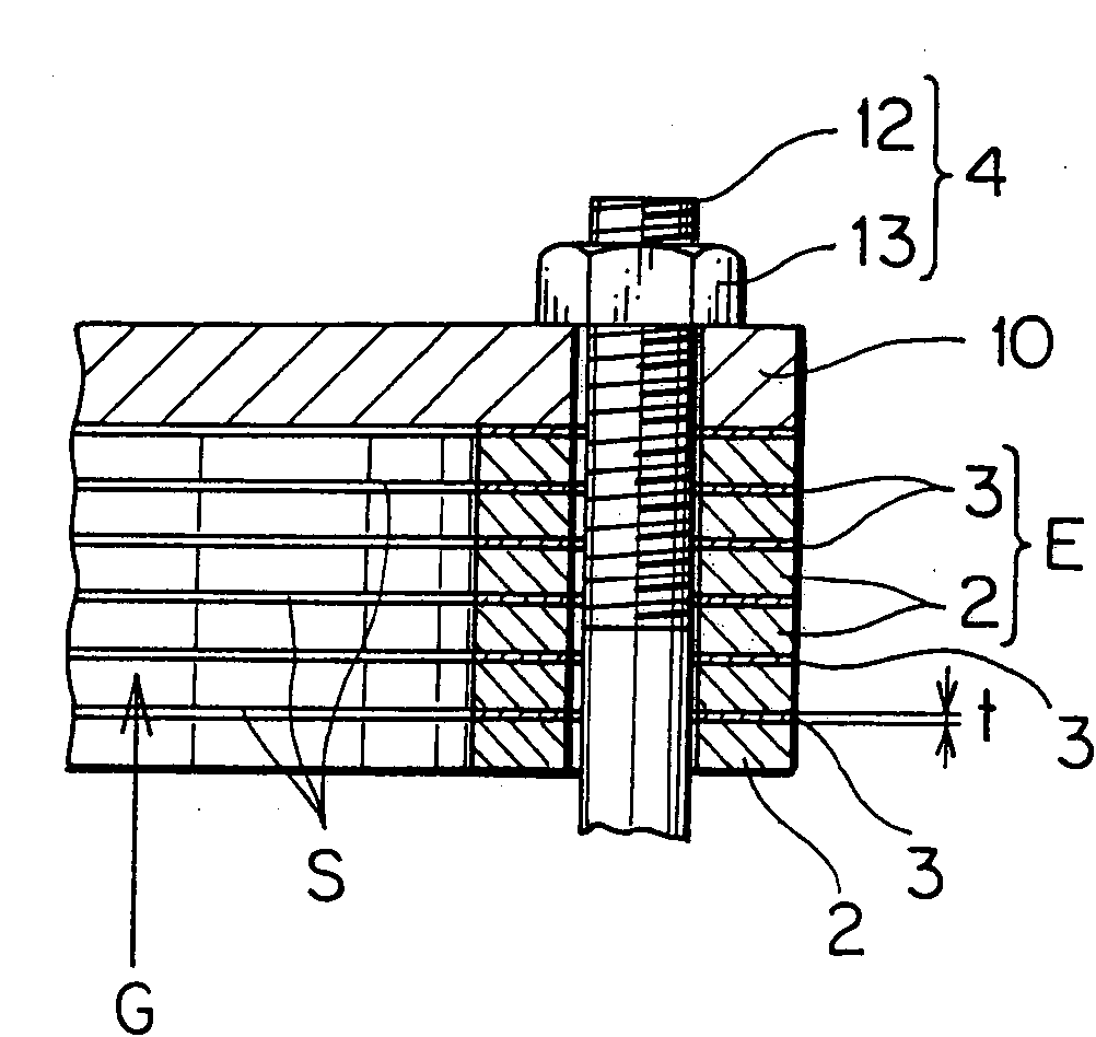
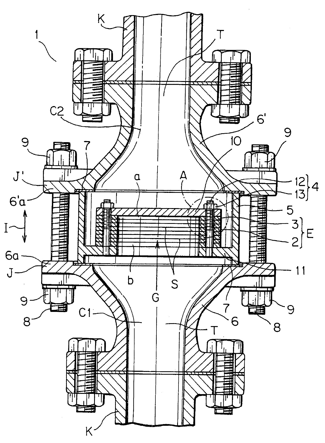
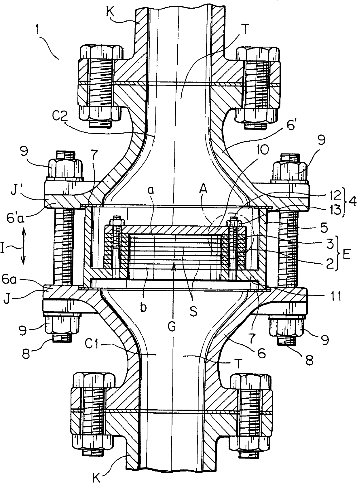
[0017] figure 1 and figure 2 Embodiment 1 of the flame arrester according to the present invention is shown. The flame arrester of this embodiment is installed in the pipe K through which the combustible gas G flows, so as to prevent the reverse flow from the downstream side C2 to the upstream side C1 of the flame generator. The flame arrester is characterized by having a drum-shaped body E comprising a plurality of annular plates 2 . The annular plates are stacked with a plurality of spacers 3 therebetween, defining slits S between the annular plates. The drum-shaped body has a first end b open to the upstream side C1 and a second end closed to the downstream side, while the slit is open to the downstream side.

[0018] The flame arrester 1 of this embodiment 1 is installed in the flow channel, such as the open end or the middl...


PUM


Abstract

A flame arrester (1) is constructed for a flammable gas (G) to prevent a reverse flow from a downstream side (C2) to an upstream side (C1) of the flame arrester. The flame arrester has a drum body (E), and the drum body has a plurality of ring plates (2). The ring plates are layered one another with a plurality of spacers (3) therebetween to define slits (S) between the ring plates. The drum bodyhas a first end (b) open to the upstream side and a second end (a) closed to the downstream side, while the slits are open to the downstream side.

Description

[0001] This application is a divisional application of the invention patent application "flame arrester" with the filing date of September 15, 2004 and the application number of 200410079157.4. technical field [0002] The present invention relates to a flame arrester, such as a flame arrester placed in a pipe or in an open end or in an intermediate portion of an exhaust system for combustible gases. The flame arrester is most suitable for preventing the intrusion of external flames and preventing deflagration or explosion caused by them. Background technique [0003] Traditionally, corrugated belt units have been used as flame arresters, for example, placed in ducts or in open ends or in mid-sections of exhaust systems for combustible gases, to block the intrusion of external flames and thereby prevent the cause deflagration or explosion. The corrugated belt unit (for example, disclosed in Japanese Patent Laid-Open No. S-63-6589) has a corrugated belt defined by bending a ...

Claims


Application Information

Patent Timeline
Patent Type & Authority Applications(China)
IPC IPC(8): A62C4/02F23D14/82
CPCA62C4/02F23D14/82
Inventor 细田秀人香川俊春
Owner KANEKO SANGYO CO LTD
Why Eureka
Try Eureka