
Tooling clamp for spanner slab

A tooling fixture and wrench technology, applied in the direction of manufacturing tools, clamping, positioning devices, etc., can solve the problems of low machining accuracy and easy movement of wrench blanks, and achieve the effect of ensuring machining accuracy and avoiding movement.

Inactive Publication Date: 2011-10-05
ZHANGJIAGANG YUCHENG MASCH C0 LTD
View PDF0 Cites 0 Cited by
  • Summary
  • Abstract
  • Description
  • Claims
  • Application Information

AI Technical Summary

Problems solved by technology

[0002] In the existing tooling fixture for wrench blanks, the wrench blank is clamped between the fixed splint and the movable splint, and the transverse direction of the head of the wrench blank extends along the vertical direction. The left and right sides of the blank are in close contact with each other to realize the clamping of the wrench blank. However, in the process of drilling or milling the wrench blank, the wrench blank is prone to movement due to unstable positioning, resulting in low machining accuracy.

Method used


Image

  • Tooling clamp for spanner slab
  • Tooling clamp for spanner slab
  • Tooling clamp for spanner slab

Examples


Embodiment Construction

[0012] The present invention will be further described below in conjunction with the accompanying drawings.

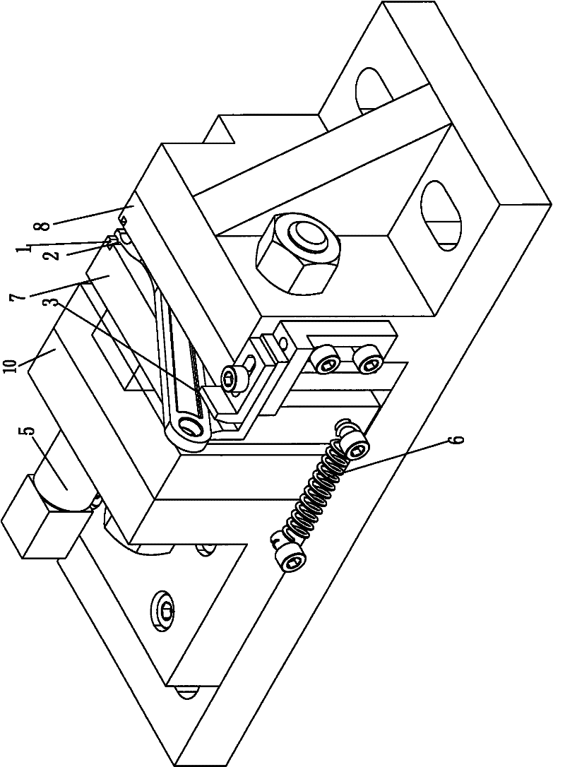
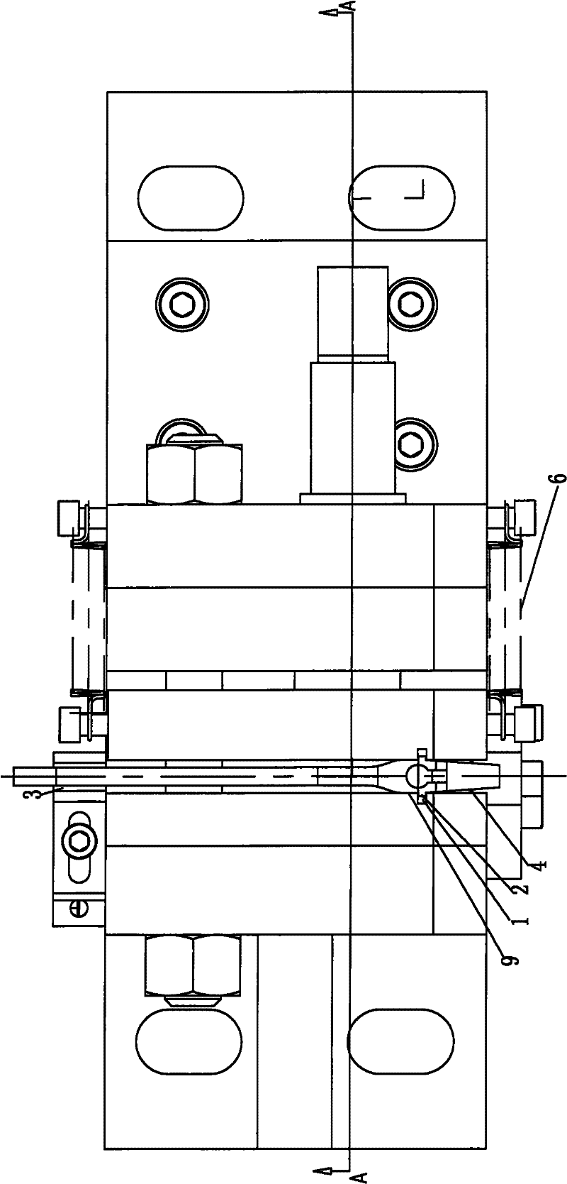
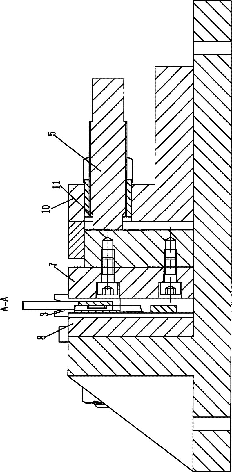
[0013] see figure 1 As shown, a tooling fixture of a wrench blank is shown in the form of a perspective view. The tooling fixture has a fixed splint 8 and a movable splint 7 that can move left and right relative to the fixed splint 8. The fixed splint 8 and the movable splint 7. There are respectively vertically arranged grooves 1 on the opposite surfaces that match the convex strips 2 extending along the transverse direction of the wrench blank head. The opposite surface is inclined and set away from the bottom to the top, so that when the fixed wrench blank is installed, the convex strips 2 on the left and right sides of the wrench blank are placed in the groove 1 of the fixed splint 8 and the movable splint 7, and the tail of the wrench blank Then it is clamped between the opposite inclined surfaces on the tail bracket 3. This method helps to realize the precise po...


PUM


Abstract

The invention discloses a tooling clamp for a spanner slab. The clamp comprises a fixed clamping plate and a movable clamping plate capable of being opened and closed leftwards and rightwards relative to the fixed clamping plate. Ribs on the left and right side surfaces of the spanner slab are matched with grooves on the opposite sides of the fixed clamping plate and the movable clamping plate; the roots of the ribs on the left and right side surfaces and the tops of convex blocks on the left and right side surfaces are respectively propped against the fixed clamping plate and the movable clamping plate; and the head of the spanner slab is supported on a head support block while the tail of the spanner slab is clamped between the opposite inclined surfaces of a pair of tail support blocks. The tail of the spanner slab is supported by the opposite inclined surfaces of the pair of tail support blocks so that the spanner slab is stably located between the fixed clamping plate and the movable clamping plate of the tooling clamp and does not move during the follow-up processing of the spanner slab, therefore, the processing precision is ensured.

Description

technical field [0001] The invention relates to a tooling fixture for a wrench blank. Background technique [0002] In the existing tooling fixture for wrench blanks, the wrench blank is clamped between the fixed splint and the movable splint, and the transverse direction of the head of the wrench blank extends along the vertical direction. The left and right sides of the blank are in close contact with each other to realize the clamping of the wrench blank. However, in the process of drilling or milling the wrench blank, the wrench blank is prone to movement due to unstable positioning, resulting in low machining accuracy. Contents of the invention [0003] The purpose of the present invention is to provide a fixture for stably positioning the wrench blank. [0004] In order to achieve the above object, the technical solution adopted in the present invention is: the tooling fixture of the wrench blank, the left and right sides of the head of the wrench blank respectively...

Claims


Application Information

Patent Timeline
Patent Type & Authority Patents(China)
IPC IPC(8): B23Q3/06
Inventor 张玉飞夏小帅黄胜男顾玉香
Owner ZHANGJIAGANG YUCHENG MASCH C0 LTD
Learn More