Touch screen adopting an optical module system using linear infrared emitters

An optical module and infrared technology, applied in the input/output process of data processing, instruments, electrical digital data processing, etc., can solve the problems of complicated manufacturing process, difficult to apply, limited scope of application, etc., and achieve low cost and simple setting , the effect of simple structure

Inactive Publication Date: 2011-01-19
HOGAHM TECH
View PDF1 Cites 17 Cited by
  • Summary
  • Abstract
  • Description
  • Claims
  • Application Information

AI Technical Summary

Problems solved by technology

[0013] When using an optical fiber as an optical waveguide, although the radius of curvature can be reduced to a certain extent, it cannot be bent sharply at a right angle
When using this kind of fiber, high manufacturing cost is required, and the manufacturing process will become complicated
[0014] In this way, if an optical waveguide is used on a touch panel formed in a small and limited rectangular space, since the angular curvature radius of the optical waveguide needs to be set to be large, there is a problem that it is practically difficult to apply
[0015] In addition, although this existing technology can use two optical modules to identify a single touch point, it cannot identify multi-point touch, so the scope of application is limited

Method used


Image

  • Touch screen adopting an optical module system using linear infrared emitters
  • Touch screen adopting an optical module system using linear infrared emitters
  • Touch screen adopting an optical module system using linear infrared emitters

Examples


Embodiment Construction

[0040] Hereinafter, preferred embodiments of the present invention will be described in detail with reference to the drawings.

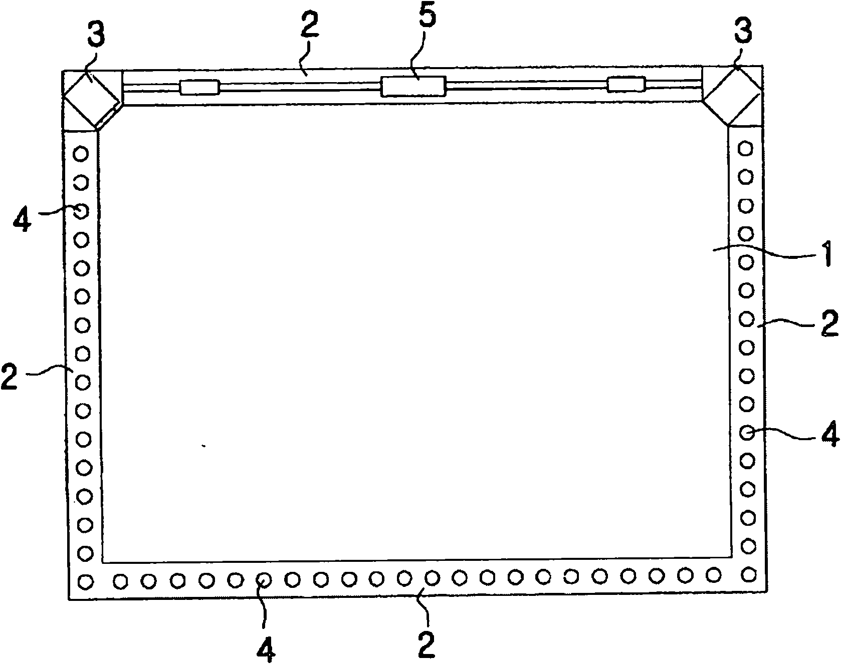
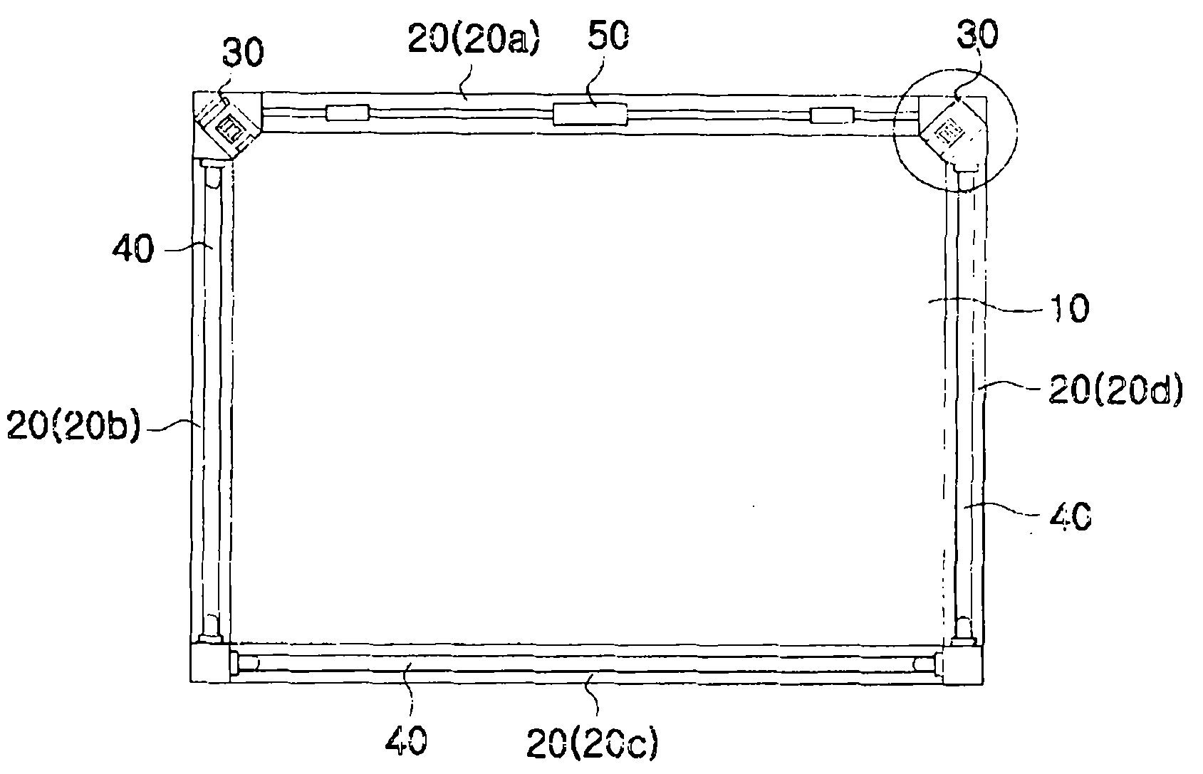
[0041] image 3 It is a schematic diagram of an optical module touch screen using a linear infrared light emitter according to an embodiment of the present invention. The touch panel to which the present invention is applied is an optical module type touch panel, and is generally suitable for a screen having a size of 20 inches or more.

[0042] Such as image 3 As shown, the touch screen in the form of an optical module according to the present invention includes: linear infrared light emitters 40 respectively arranged on the three sides 20b, 20c, and 20d of the frame 20 supporting the rectangular screen 10 for emitting infrared rays; The small optical module 30 provided with the two ends of the remaining one side 20a of the linear infrared light emitter 40 is used to detect the infrared rays emitted from the linear infrared light emitter 40; the ...


PUM


Abstract

The present invention relates to a touch screen adopting an optical module system using linear infrared emitters, wherein linear infrared emitters are arranged on three or four sides of a rectangle constituting the touch screen, two or three optical modules are employed to sense the infrared light emitted from the linear infrared emitters, and the shadow generated by the touch of fingers is recognized to detect the location of the touch. The touch screen adopting an optical module system using linear infrared emitters according to the present invention comprises: linear infrared emitters (40) arranged independently on at least three sides (20b, 20c, 20d) of the four sides (20) of a rectangular screen (10) to emit infrared light; optical modules (30) arranged on at least two corners of the four corners of the rectangular screen (10) to monitor the whole of the screen (10) and sense the infrared light emitted from the linear infrared emitters (40); and a control board (50) which analyzes the infrared signal sensed through the optical modules (30) to detect the point on the screen touched by the user.

Description

technical field [0001] The invention relates to a touch screen in the form of an optical module, in particular to arranging linear infrared luminous bodies on three or four sides of a rectangular frame constituting the touch screen, and using two or three optical modules to detect linear infrared luminous bodies. The infrared light emitted by the illuminant can identify the shadow generated by the touch of the finger, thereby determining its position. A touch screen using an optical module of a linear infrared illuminant. Background technique [0002] A touch screen is a device capable of specifying a touch point in response to the touch when an image displayed on the screen is touched (contacted) with a finger, a stylus pen, or the like. [0003] Generally, a touch screen is manufactured as a structure overlaid on a flat display LCD panel or a PDP panel, and the touch screen is a device that specifically recognizes the touch position of a finger and converts it into coordin...

Claims


Application Information

Patent Timeline
Patent Type & Authority Applications(China)
IPC IPC(8): G06F3/041
CPCG06F3/0428G06F3/03547G06F3/0412G06F3/0416
Inventor 张根浩赵东焕郑英镇
Owner HOGAHM TECH
Why Eureka
Try Eureka