
Plant trimmer

A technology for trimmers and plants, applied in the field of chainsaws, can solve the problems of difficulty in applying force by operators, laborious operation process, and laborious operation.

Active Publication Date: 2011-01-26
POSITEC POWER TOOLS (SUZHOU) CO LTD
View PDF2 Cites 7 Cited by
  • Summary
  • Abstract
  • Description
  • Claims
  • Application Information

AI Technical Summary

Problems solved by technology

However, this structure makes the operation not very comfortable in some cases. For example, when it is necessary to cut high branches, it is more difficult for the operator to apply force; in addition, when it is necessary to cut wood placed on the ground, the operator needs to bend Work with your lower back, which can easily tire you if you work for a long time
[0005] In addition, if the branches on the taller trees are to be cut, this traditional chain saw usually includes an extension rod, which is usually detachably fixedly connected to the main handle of the chain saw. During operation, the operator holds the extension rod , applying force in the cutting direction, this operation is often laborious
[0006] U.S. Patent No. US7152328B2 discloses a chain saw including a working head, a main handle and an extension rod. When cutting higher branches, the user fixes the extension rod to the main handle, and the extension rod is electrically connected to the main handle. The user can operate as long as he holds the extension rod, but when operating this kind of chain saw, the operator needs to apply a large force in the cutting direction, which will make the operation process more laborious

Method used


Image

  • Plant trimmer
  • Plant trimmer
  • Plant trimmer

Examples


Embodiment Construction

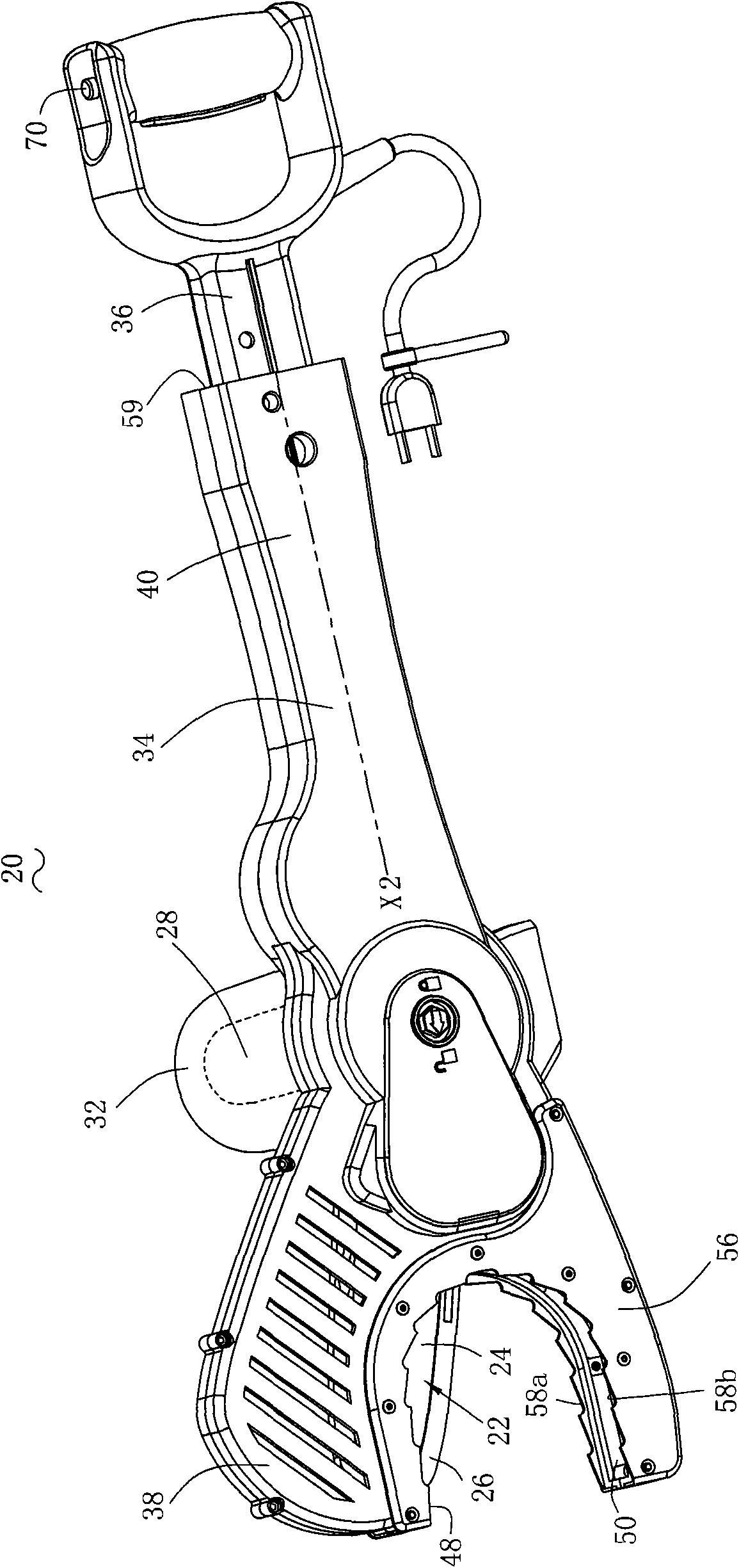
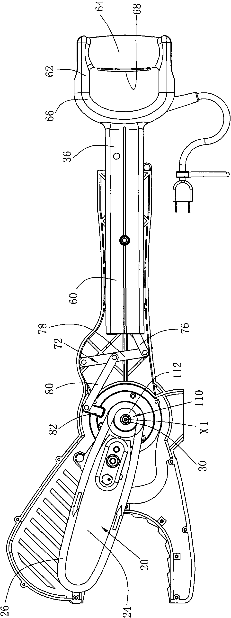
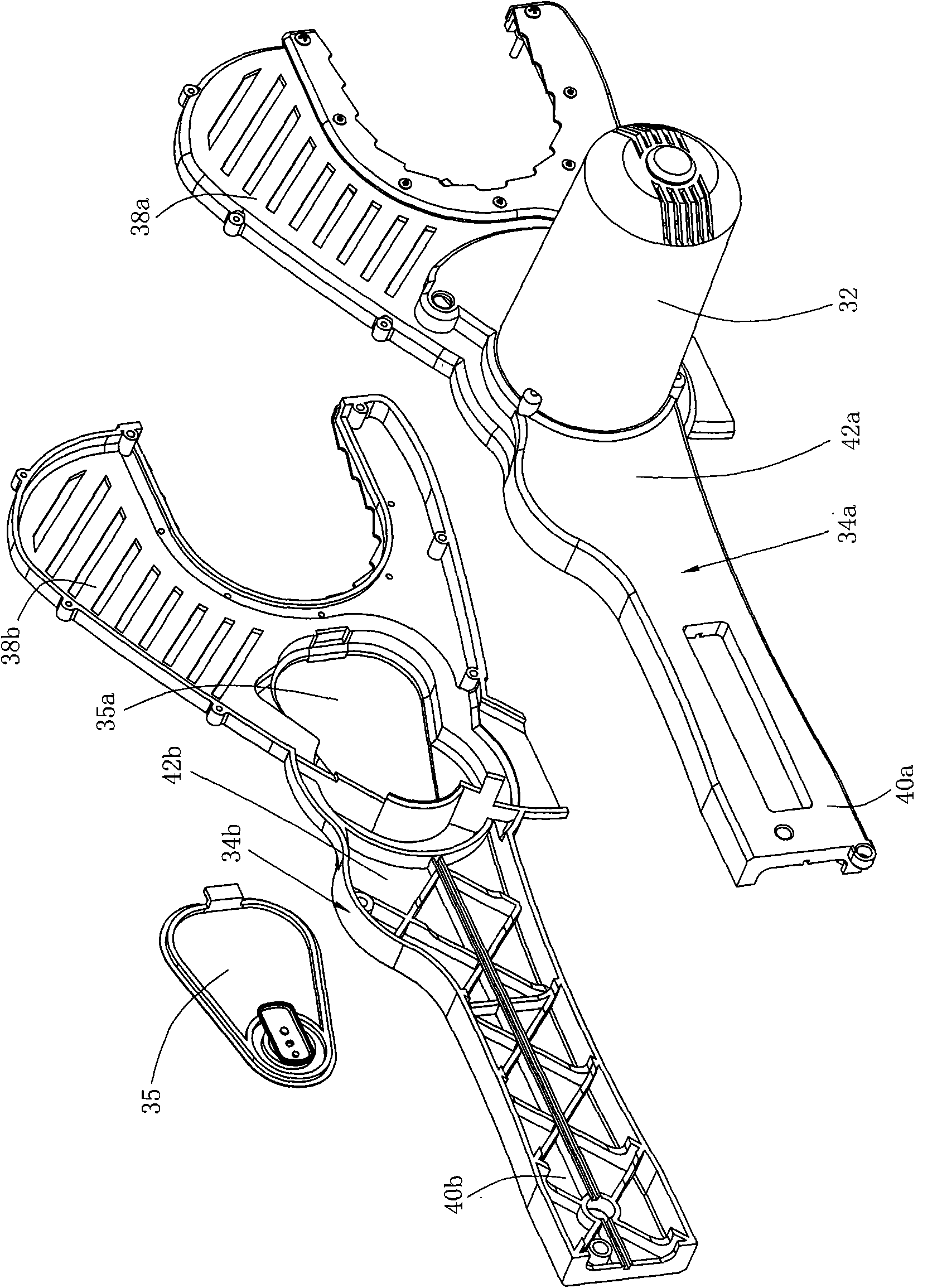
[0107] Figure 1 to Figure 2 A plant pruning machine is disclosed. In one embodiment of the present invention, the plant pruning machine is a chain saw 20. The chain saw 20 includes a working head 22 for processing workpieces. The working head 22 includes a support plate 24 and is mounted on the support plate. 24 cutting elements. In this embodiment, the cutting element is a flexible chain 26 , which is installed on the periphery of the support plate 24 and can rotate around the support plate 24 . The plane where the support plate 24 is located is the support plate plane. In other embodiments of the invention, the working head may be a saw blade of a circular saw, a reciprocating saw, or the like. When the working head is a circular saw blade, the cutting element can be considered as the cutting part of the circular saw blade and the support plate can be considered as the central support part of the circular saw blade. When the working head is a saw blade like a reciprocati...


PUM


Abstract

The invention provides a plant trimmer, which comprises a cutting element, a supporting plate for supporting the cutting element, a motor for driving the cutting element, a first handle component, a second handle component, a locking mechanism for fixing and connecting the second handle component with the first handle component in a detachable manner, and a connecting mechanism between the first handle component and the supporting plate, wherein the first handle component or the second handle component performs an linear motion toward or away from the supporting plate in an operable manner; and the connecting mechanism converts the linear motion of the first handle component or second handle component into the swinging of the supporting plate.

Description

technical field [0001] The present invention relates to a plant trimmer, in particular to a plant trimmer with an extension bar, such as a chain saw with an extension bar. Background technique [0002] At present, there are many tools for pruning plants on the market, such as scissors for pruning some relatively small branches and leaves. There are also pruners and chain saws that are usually used to trim relatively thick trees and so on. [0003] A traditional chainsaw includes a working head consisting of a chain and a support plate used to support the chain. The chain is driven by a motor and rotates around the support plate. The traditional chainsaw also includes a main handle located at the rear of the work head. Auxiliary handle between head and main handle. When cutting, the working head of this traditional chain saw is usually only driven by the motor so that the chain rotates around the support plate, and the support plate is generally stationary. During the cutti...

Claims


Application Information

Patent Timeline
IPC IPC(8): A01G3/08
CPCB27B17/0083B27B17/0008A01G3/086B27B17/02
Inventor 沃伦·布朗哈利·索默格雷厄姆·格哈德
Owner POSITEC POWER TOOLS (SUZHOU) CO LTD
Learn More